Do you have a question about the DIMAT TPU-1 and is the answer not in the manual?
Symbol denotes a hazard. Incorrect procedure may cause equipment breakdown or injury.
Information or important aspects to take into account in a procedure or operation.
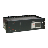
Explains the capacity of the shelf and the fixed positions for modules.
Provides step-by-step instructions for safely removing and installing modules.
Explains the meaning of different LEDs for system status, power, and interface links.
Details the meaning of additional LEDs for TP channels, alarms, and commands.
Describes the functionality and interaction with the optional LCD display.
Details configuration elements and default IP/passwords for the MWTU module.
Explains jumper settings for nominal voltage configuration of IPTU module input circuits.
Describes jumper settings for output impedance and cable shield connection in IDTU modules.
Details jumper settings for nominal voltage configuration of DSTU module input optocouplers.
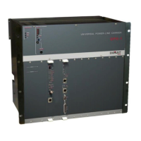
Details the ATPU power-supply module and its alarm relay connections.
Describes connectors for LAN interface and GPS time synchronization on the MWTU module.
Introduces different types of analog and digital line interface modules.
Details the 64 kbit/s interface and connector pin assignments for the IETU module.
Describes the 2 Mbit/s interface and connectors for the IDTU module.
Details the 64 kbit/s optical fiber interface and connectors for the IOTU module.
Describes the 2 Mbit/s optical fiber interface and connectors for the IOCT module.
Details the IP communications interface module and its connectors.
Describes analog line interface modules for single or dual tone transmission.
Details the connector pin assignments for IPTU protection-side interface modules.
Describes the IEPT module for IEC 61850 communication with protection terminals.
Explains IRTU modules for increasing auxiliary outputs and their configurability.
Covers MCTU and DSTU modules for analog measurements and digital signals.
Lists essential checks to perform before and during terminal startup.
Instructions for configuring IPTU modules and handling static sensitive components.
Describes the procedure for powering on the terminal and initial self-check.
Explains how to modify web server network parameters like IP address.
Details the configuration of the management computer for PC-terminal connection.
Lists hardware and software requirements for the management computer.
Details the 10/100Base-TX LAN interface and cable requirements.
Pin assignment for the RJ-45 connector used in the LAN interface.
Shows the structure of UTP-5 cables and their RJ-45 connector according to standards.
Illustrates the wiring of a crossover cable for direct PC-terminal connection.
Illustrates the wiring of a straight-through cable for hub/switch connections.
Details the 100Base-FX LAN interface using optical fiber and MT-RJ connector.
Shows optical power characteristics for different multi-mode fiber types.
Steps for configuring Web Management from the LAN interface.
Instructions for configuring browser settings and accessing the web server.
Shows the login screen for web management access.
Details user identification, password, and security message procedures.
Explains the security warning and file execution for system access.
Options for closing the web management session and saving data.
Differentiates between online and offline management methods.
Procedure for updating web pages and browser cache after updates.
Procedure for verifying power supply voltage and polarity with a multimeter.
Steps to test command inputs and outputs using the Management System.
Verifying analog line signal levels using a selective voltmeter.
Procedures for testing the teleprotection link, including loops and command transmission.
Verifying connections and operation of alarm and signalling relays.
Performing final checks, including unblocking, deactivating loops, and resetting counters.
Details packaging methods, weight limits, and transport specifications.
Guidelines for storing TPU-1 terminals, including environmental conditions and stacking.
Illustrates the structure and decimal format of an IP address.
Describes the different classes (A, B, C) of IP addresses based on network/host bits.
Explains how subnet masks determine network and host parts using an AND operation.
Discusses device communication within LANs and the role of the default gateway.
Outlines key features like object-oriented modeling and protocol stacks.
Explains how IPTU modules and line interfaces determine the number of terminal blocks.
Details the ZATU.00 terminal block for the ATPU power-supply module.
Details the ZPTU.00 terminal block for the IPTU protection-side interface module.
Describes the ZDTU.00 terminal block for the IDTU digital line interface module.
Details the ZETU.00 terminal block for the IETU digital line interface module.
Details the ZITU.00 terminal block for IATU/IBTU analog line interface modules.
Describes ZRTU terminal blocks associated with IRTU relay interface modules.
Details ZCTU.01 terminal blocks for the MCTU current measurement module.
Details ZSTU.00 terminal blocks for the DSTU digital signal I/O interface module.
Shows configurations for cabinet-mounting terminal blocks with digital and IPTU modules.
Illustrates terminal block setup for a digital channel and analog (IPTU) modules.
Shows terminal block setup for two analog channels and IPTU modules.
Illustrates terminal block setup for one analog channel and two relay interface modules.
Depicts additional cabinet-mounting terminal blocks for eight IPTU modules.
Provides overall dimensions for cabinet-mounting terminal blocks.
Explains how to activate and use the optional LCD display and its buttons.
Displays system network information like IP address, mask, and gateway.
Shows network parameters specific to the IEC 61850 interface.
Displays network parameters for IP interfaces like TP1 and TP2.
Lists general system alarms such as Startup, Module, and RTC status.
Shows specific alarms, like Power Failure, for the terminal.
Displays counters for input activations on the terminal.
Displays counters for output activations on the terminal.
Shows counters for command transmissions on communication channels.
Displays counters for command receptions on communication channels.
Indicates the loop status when no loops are active.
Shows the loop status when loops are active (INTERNAL/LINE).
Displays the blocking status of the terminal via a padlock symbol.
| Brand | DIMAT |
|---|---|
| Model | TPU-1 |
| Category | Touch terminals |
| Language | English |