Communication solutions for power utilities
UNIVERSAL TELEPROTECTION TPU-1
INSTALLATION AND COMMISSIONING MANUAL Web version TPU-1R - Rev. 5.9 (May 2018)
4.2 PROCESSING MODULE
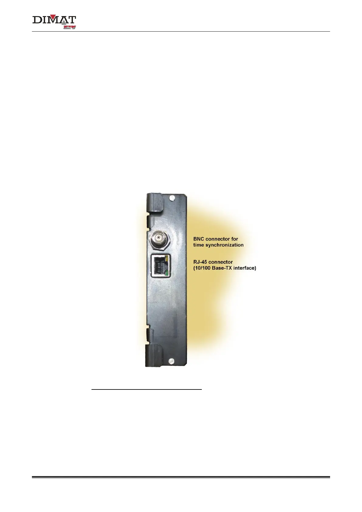
Figure 13 shows a front view of the MWTU module. As can be seen in the figure, there are
two connectors on the front plate, one for the 10/100 Base-Tx or 100Base-Fx interface and
the other one for connection to a GPS synchronized time equipment.
The BNC connector allows the TPU-1 terminal to synchronize its internal real time clock with
the time reference given by any GPS synchronized time equipment that has an IRIG-B
standard output.
The operation of the RJ-45 (10/100Base-Tx interface) or MT-RJ (100Base-Fx interface)
connector must be established from the Management System.
Make sure that the module is completely fixed to the chassis.
LEDs associated with the RJ-45 connector
• Amber. It stays on when the link is established correctly.
• Green. It flashes in the case of activity in the interface.
Figure 13 MWTU processing module connector