Communication solutions for power utilities
UNIVERSAL TELEPROTECTION TPU-1
INSTALLATION AND COMMISSIONING MANUAL Web version TPU-1R - Rev. 5.9 (May 2018)
1 MECHANICAL CHARACTERISTICS
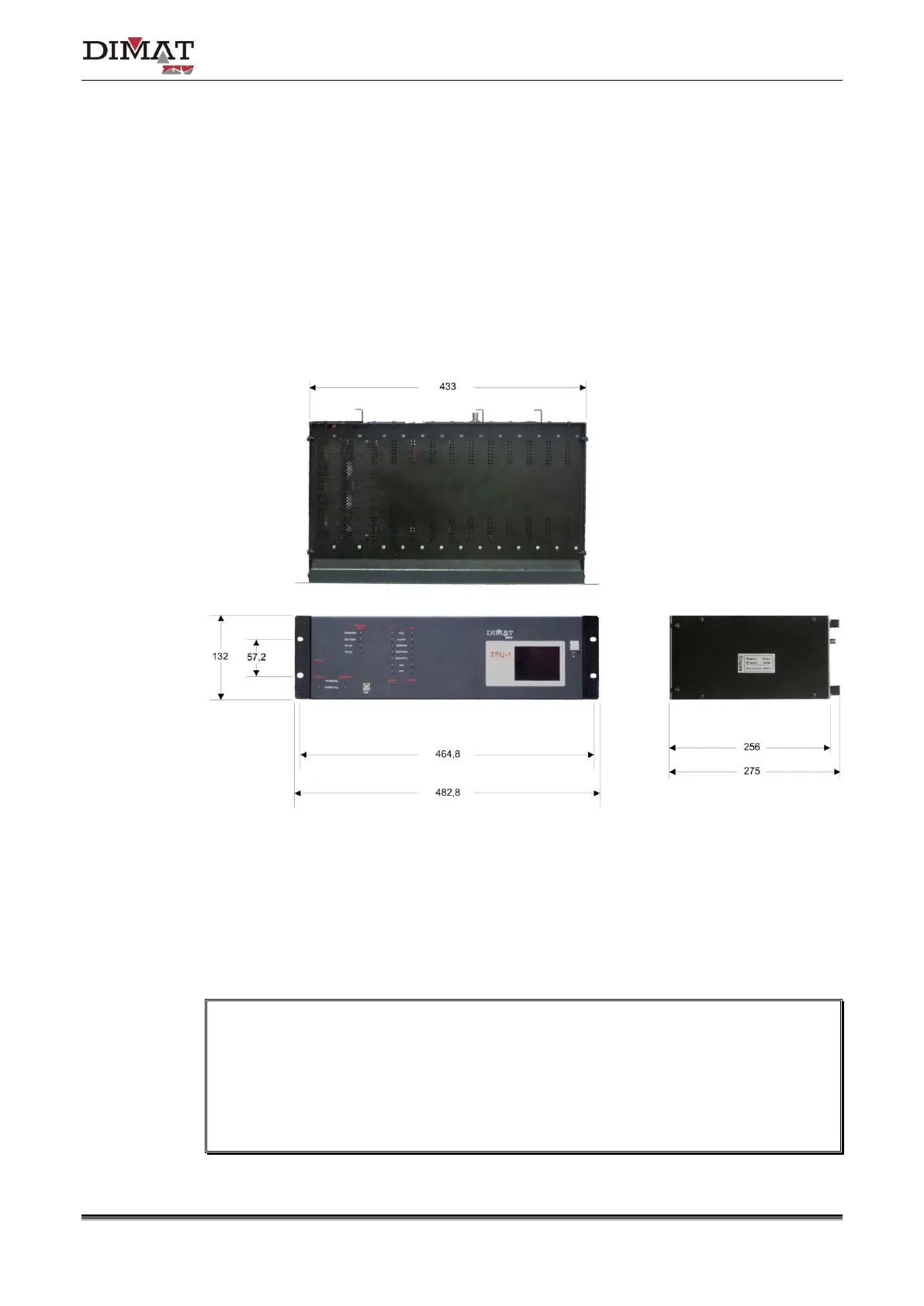
The TPU-1 terminal is made up of a 19” shelf that is 3 standard units (s.u.) in height,
prepared for rack mounting.
Figure 1 shows the general dimensions of the shelf as well as the position of the fastening
holes. As can be seen in the figure, the shelf has one ventilation grid.
Figure 1 General dimensions of the TPU-1 shelf
The input and output of signals is carried out by means of the plug-in connectors located at
the rear of the shelf. If one wishes the external connections to be carried out through a
cabinet-mounting terminal block, it can be supplied on request, together with the necessary
cables, see Appendix C.
During installation it must be made sure that the ventilation grid is NOT covered. Once
the shelf has been installed, it must be checked that the ventilation grid on the top is NOT
obstructed in any way.
When installing the terminal in a frame of a cabinet, in order to improve ventilation, a
space equivalent to at least one standard unit must be left above and below it.