Communication solutions for power utilities
UNIVERSAL TELEPROTECTION TPU-1
INSTALLATION AND COMMISSIONING MANUAL Web version TPU-1R - Rev. 5.9 (May 2018)
3.2 PROTECTION-SIDE INTERFACE MODULES
(CIRCUITS FROM ONE TO TWO COMMANDS)
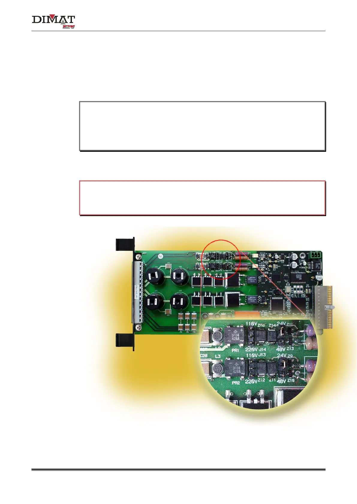
Each protection-side interface module (IPTU) has two independent input circuits whose
activation can be established, by means of jumpers, for a nominal voltage of 24, 48, 110 or
220 V
DC
.
Once the nominal voltage has been established, the minimum voltage that guarantees
the input activation is 19 V
DC
for 24 V
DC
, 38 V
DC
for 48 V
DC
, 88 V
DC
for 110 V
DC
and
176 V
DC
for 220 V
DC
, and the maximum voltage that guarantees NON input activation is
14 V
DC
for 24 V
DC
, 29 V
DC
for 48 V
DC
, 66 V
DC
for 110 V
DC
and 132 V
DC
for 220 V
DC.
Figure 7 shows the position of the input-activation nominal-voltage configuration jumpers in
the IPTU module.
Under NO circumstances must the maximum operating voltage be exceeded, being:
29 V
DC
for 24 V
DC
, 58 V
DC
for 48 V
DC
, 132 V
DC
for 110 V
DC
and 264 V
DC
for 220 V
DC
.
a) Model A