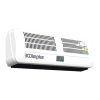
Operation
1. Switch on electricity supply to the heater.
2. Switching the switch marked " "
energises blower and illuminates neon
indicator.
3. Select " " and switches marked " xx " and
" xx xx " as required :-
Switch : Cooling
+ xx : half heat
+ xx xx : half heat
+ xx + xx xx : full heat
NOTE: When remote control switch is fitted,
ensure that all three appliance switches are
switched to the "ON" position.