EasyManua.ls Logo

Dimplex AC3 User Manual

Dimplex AC3
4 pages
To Next Page IconTo Next Page
Page #1 background imageLoading...
Page #1 background image
Air Curtain
Model AC3 and Model AC45
IMPORTANT
These instructions should be read and carefully retained
by the user.
The installation of this appliance should be carried out by a
competent electrician and be in accordance with the current
IEE wiring regulations. Tools required are an electrical
screwdriver with a 3mm wide blade, a No 2 posidriver, a
7mm AF open ended or box spanner, an 8mm AF open
ended spanner.
Installation and Operating
Instructions
DO NOT COVER OR OBSTRUCT the air inlet or outlet
grille.
Special instructions on fitting the heater to
a wall or ceiling:-
Solid brick or concrete block walls must be drilled and
plugged with Rawlplug No 10 size FIBRE inserts. The plug
must be located in the solid part of the wall, not just in the
plaster layer.
For panelled internal walls or ceilings, it is best to locate
the studding, position the heater fixing bracket accordingly
and use No 10 size wood screws. If it is not possible to
locate the studding, use type M5 Rawlplug INTERSETS,
making the 10mm holes with a drill rather than a bradawl or
a screwdriver.
Fixing Positions
Ceiling
mounting
Wall
mounting
Heaters may be mounted end to
end for wide doorways.
Installation
1 (a) Remove front louvered panel by
removing two screws on top flange.
1 (b) If the electricity supply to the heater
is required via conduit entry or through
the remote control switch, it will be
necessary to remove the knockout
around the cable entry bush to provide
a 2Omm diameter hole.
Question and Answer IconNeed help?

Do you have a question about the Dimplex AC3 and is the answer not in the manual?

Dimplex AC3 Specifications

General IconGeneral
BrandDimplex
ModelAC3
CategoryAir Conditioner
LanguageEnglish

Summary

Installation and Operating Instructions

Air Curtain Models AC3 AC45

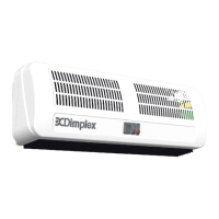
Identifies the specific air curtain models covered by these instructions.

Special Wall and Ceiling Fitting Instructions

Provides specific guidance for securely mounting the heater onto different wall and ceiling types.

Fixing Positions

Ceiling Mounting

Details the procedure and considerations for installing the heater in a ceiling configuration.

Wall Mounting

Details the procedure and considerations for installing the heater in a wall-mounted configuration.

Installation Steps

Removing Front Panel

Instructions on how to remove the front louvered panel by unscrewing it from the top flange.

Conduit Entry Preparation

Guidance on preparing the knockout for cable entry if using conduit or a remote control switch.

Mounting Bracket Installation

Steps for removing and fixing the mounting bracket to the wall or ceiling.

Heater Mounting and Angle Adjustment

Procedure for attaching the heater to the bracket and adjusting its angle.

Electrical Connection

Details on connecting the heater to the fixed wiring and mains supply terminal.

Securing Terminal Bracket and Cover

Instructions for re-securing the mains supply terminal bracket and the front cover.

Circuit Diagrams

AC3 Heater Circuit Diagram 1

Wiring diagram for the AC3 heater showing internal component connections.

AC45 Heater Circuit Diagram 1

Wiring diagram for the AC45 heater showing internal component connections.

AC3 Remote Control Switch Circuit Diagram 2

Wiring diagram for the AC3 heater with a remote control switch.

AC45 Remote Control Switch Circuit Diagram 2

Wiring diagram for the AC45 heater with a remote control switch.

Operation

Switching On and Blower Activation

Procedure for switching on the heater and activating the blower and neon indicator.

Heat and Cooling Selection

Instructions on selecting cooling mode, half heat, or full heat settings.

Remote Control Switch Operation

Note on ensuring all appliance switches are 'ON' when a remote control switch is fitted.

Maintenance and Safety

WARNING: Disconnect Supply

Crucial safety warning to disconnect power before performing any maintenance.

Thermal Safety Cut Outs

Explanation of thermal cut-outs, their triggers (overheating reasons), and reset procedure.

Cleaning Instructions

Guidance on maintaining the external appearance and internal cleanliness of the heater.

After Sales Service

Information on the one-year guarantee, service procedures, and contact details.

Related product manuals