If the power cord of this heater is damaged, it must be
replaced.; a special new power cord is available from the
manufacturer or the after-sales service.
4. Heating Operation
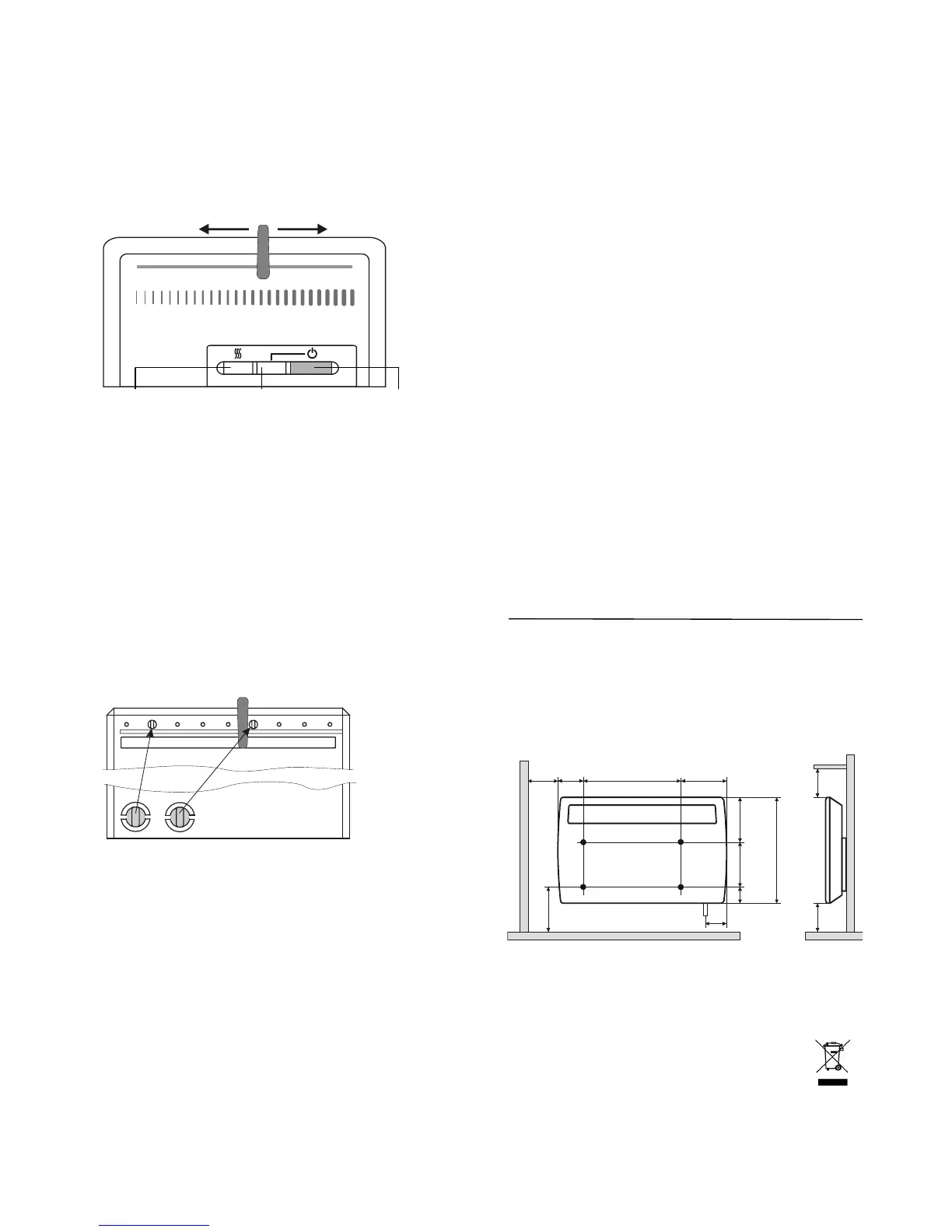
The heater is switched on and off by means of the power
switch. The right indicator light (B) is illuminated when the
appliance is switched on.
MAX
*
Indicator light (A) Indicator light (B) Power switch
"Heating On“ "Device On“ On/Off
4.1 Thermostat
The heater is fitted with an electronic thermostat by means of
which the room temperature can be controlled by choosing a
suitable setting. The ∗ setting corresponds to a room
temperature of approx. 6 °C (frost protection setting). To
increase the temperature, move the slide switch to the right.
The left indicator light (A) is illuminated when the heater is in
the heating mode.
4.3 Limiting the Thermostat Setting Range
The setting range of the thermostat can be defined by means
of the two limiting pins (A) provided on the heater rear panel.
One pin each is provided for limiting the upper and lower
value.
The pins can be removed by moving them back and
forth, e.g. by means of flat nose pliers, and be inserted
into the holes in the thermostat.
5. Overheat Protection
The heater is equipped with an overheat protection for your
safety. If the air circulation is impeded, the heater is switched
off by the overheat protection. Once the heater has cooled
sufficiently, it will automatically switch on again.
In the event that the overheat protection trips repeatedly, the
cause of overheating must be determined, e.g. air grille is
covered or obstructed.
For maximum heat output it is essential that you keep the air
inlet and outlet openings free of dust. Clean the heater with a
vacuum cleaner before the start of the heating season!
6.Malfunctions
If there is no heat output from the unit, please check that the
heater is switched on and that the thermostat is set to the
desired temperature. Subsequently check the circuit breaker
on the main service panel, or the fuse, to ensure that they
have not tripped or blown.
When a programming cassette is used check that the
program "ON" is active (also refer to the operating instructions
of the programming cassettes on the pages that follow).
If the fault cannot be corrected, please consult the nearest
after-sales service agent.
For processing the service call, the product number (E-
number) and the manufacturing date code (FD-number) of the
heater are required. These data can be found on the rating
plate.
Any repairs and interventions in the heater may only be
performed by a qualified electrician or the after-sales service.
7. Cleaning
Before cleaning make sure that the heater is disconnected
from the power supply and that it has cooled down. Wipe the
outside of the heater with a soft, damp cloth. Do not use any
scouring powder or furniture polish for cleaning as these may
damage the surface.
Dust that may have accumulated in the heater can be
removed from the outside with a vacuum cleaner.
8. Technical Data
Supply voltage 1/N/PE~ 230V, 50Hz
Thermostat 5-30°C
Protection class I PE conductor
Enclosure type IP 24 (splash-water protected)
Type Capacity Weight Width HeightDepth Dim. A
(all dimensions in mm)
EPX 500 500 W 5.2 kg 448 430 115 116
EPX 750 750 W 6.6 kg 618 430 115 286
EPX 1000 1000 W 6.6 kg 618 430 115 286
EPX 1500 1500 W 7.1 kg 686 430 115 354
EPX 2000 2000 W 8.5 kg 858 430 115 526
EPX 2500 2500 W 10.5 kg 858 430 145 526
118
150
150
150
65
255
214
141
184
105
430
A
9. Warranty
Authorised dealers can provide information on the terms and
conditions of warranty. The warranty is not valid without a
sales receipt marked with the date of purchase.
Disposal Notice
The product should not be disposed of with your
other household waste.
Drillin
 Loading...