Do you have a question about the Dimplex EPX Series and is the answer not in the manual?
The wall brackets supplied with the appliance must be used for installation.
Heater controls must not be reachable by someone using a bath or shower.
Do not place heater below a fixed socket outlet or connection box.
Do not cover the heater or obstruct airflow, as this risks overheating and fire.
Heater surfaces can be hot; supervise children and infirm persons.
This appliance is not for unsupervised use by children or those with reduced capabilities.
If the supply cord is damaged, it must be replaced by the manufacturer or qualified agent.
This appliance must be earthed and installed by a competent electrician per I.E.E. regulations.
BLACK control wire carries signals from programmers; isolate if not used; never connect to earth.
The supply cord's earthing conductor provides supplementary bonding as per Regulation 547-03-05.
Use only the supplied wall brackets and observe minimum clearances.
Steps to detach brackets, fix to wall, and hang the heater securely.
Use the 'ON/OFF' button to control power; an indicator shows when the unit is powered.
Adjust the thermostat slider to control room temperature from frost protection to maximum.
Allows installers to check heater response to pilot wire signals.
Installer can limit thermostat slider movement using plastic pins.
Procedure for installing optional control modules, including pre-installation steps.
Appliance has a thermal cut-out that resets automatically if overheating occurs.
Disconnect power before cleaning; use a soft damp cloth; avoid abrasive cleaners.
Product is guaranteed for two years; contact customer services for repairs or spares.
Reduce thermostat by 1°C for 10% energy saving; use heaters only where needed.
Tips include closing curtains, improving window insulation, and insulating hot water tanks.
Use showers, set water heater thermostat to 60°C, and fix dripping taps.
Turn off lights in empty rooms and use low-energy bulbs.
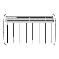
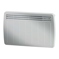
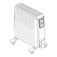
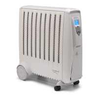
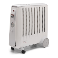
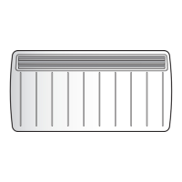
The Dimplex EPX Electronic Panel Convector Heater is a wall-mounted heating appliance designed for efficient and controlled room heating. It operates on electricity and is intended for indoor use, providing warmth through convection. The heater is designed to be operated in an upright position and is splashproof to IP24 standard, making it suitable for various indoor environments, including rooms with baths or showers, provided it is installed correctly to prevent contact with switches and controls by a person using the bath or shower.
The primary function of the EPX heater is to convert electrical energy into heat to warm a room. It features an electronic thermostat that allows users to set and maintain a desired room temperature. The heater's operation is controlled by a simple "ON" button and a slider for temperature adjustment. When the room temperature reaches the set level, the heater automatically reduces power to its elements, maintaining the chosen temperature.
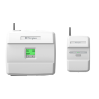
For enhanced control and energy efficiency, the EPX heater can be integrated into a pilot wire system. This allows it to receive signals from external programmers, such as Dimplex slot-in or wall-mounted programmers, to implement various heating modes like "ON," "OFF," "FROST protection," and "SETBACK" (background temperature). In "SETBACK" mode, the heater automatically operates at a room temperature setting approximately 5°C less than the thermostat setting, which is useful for maintaining a lower background temperature when a room is not actively in use.
The heater incorporates a thermal cut-out for safety, which automatically cuts power to the elements if the product overheats. Once the heater cools down, it will reset and resume normal operation, cycling on and off until the cause of overheating is resolved.
| Model | EPX Series |
|---|---|
| Frost Protection | Yes |
| Overheat Protection | Yes |
| Warranty | 2 years |
| Type | Panel Heater |
| Heat Output | 0.5kW, 1.0kW, 1.5kW, 2.0kW |
| Power Output | 0.5kW, 1.0kW, 1.5kW, 2.0kW |
| Voltage | 230-240V |
| Control Type | Electronic |
| Timer | 24-hour programmable timer |
| Mounting | Wall-mounted |
| Weight | Varies by model |