www.dimplex.com2
WARNING: Disconnect power and heater has cooled
before attempting any maintenance or cleaning to reduce
the risk of re, electric shock or damage to persons.
Remove grille and frame by removing screws “A”. Remove
two screws “B”, and slide out heating assembly. When re-
assembling, reverse the procedure above.
Cleaning
!
NOTE: This heater should not be operated with an ac-
cumulation of dust or dirt on or in the unit, as this can cause
a build up of heat and eventual damage. For this reason the
heater must be inspected regularly, depending upon condi-
tions and at least at yearly intervals.
• With grille in place - Use vacuum cleaner hose to suck
out lint and dirt around grille. Reverse hose on vacuum to
use as a blower to move dust out of enclosure. Reverse
hose back to suck out dirt at front area of heater.
• With grille removed - Remove two screws “B” at bottom
front of heating element assembly. Pull gently to remove
it from enclosure. Swing assembly out. Vacuum inside
of enclosure and around heating element assembly. Re-
verse procedure above to re-assemble unit.
Maintenance
Operation
WARNING: This heater must be properly installed before
it is used.
1. Prior to energization remove all construction dirt (plaster,
sawdust, etc.) from interior and exterior of heater.
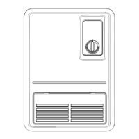
2. Adjust thermostat with pliers. This unit is also controllable
from a line voltage wall thermostat or eld installed built-
in tamperproof single or double pole thermostat kit.
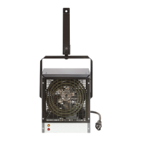
Dimplex kickspace heaters are designed and tested for safe
and trouble-free operation. All Dimplex kickspace heaters are
protected against overheating by a built-in thermal cutout.
Free airow throughout the heater is extremely important for
the most efcient operation of the heater. Restricted airow
may cause the thermal overload protector to cycle the heater
“ON and OFF”. A cycling heater will not supply sufcient heat
to the room.
Avoid direct contact of paper, fabric, or furniture with heater.
as shown in Fig.2.
4. Remove heater cover and appropriate knockout. Attach
service cable to unit with approved connector and con-
nect colour to colour in outlet box. To change wattage or
voltage connections, see Figure 4.
5. Replace cover, slide unit into opening, and secure each
side (Figure 1).
!
NOTE: Make sure unit is installed right side up. Refer
to “TOP” label.
For inspection of eld wiring, see instruction under “Electrical
Inspection”.
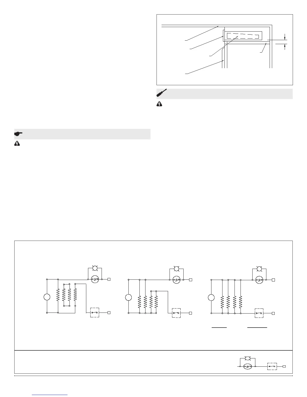
SoftorStairRiserInstallation
1. Cut opening as for kickspace installation (22 3/8” x 3
5/8”). Allow 3/4” clearance above cabinet doors. Add sup-
ports for unit (Figure 3).
2. Proceed as for kickspace installation. After securing unit
in opening, install combination of frame and grille (Figure
1).
FIGURE 3
FACTORY CONNECTION
208/240 VOLT 675/900 WATTS
3.2 A / 3.7A
FIELD CONNECTION
208/240 VOLT 1350/1800 WATTS
6.5 A / 7.5 A
FIELD CONNECTION
120 VOLT
Figure 4
FAN
FAN
FAN
MM
M
SAFETY SWITCH SAFETY SWITCHSAFETY SWITCH
IMPORTANT: RETIGHTEN ALL LEADS WITH CABLE CLAMP AFTER RECONNECTING
UNINSULATED ENDS OF UNUSED LEADS WITH WIRE NUTS
Figure 4a
THERMOSTAT
NOTE: If installing unit with factory thermostat, see supplemental wiring diagram, Fig. 4a.
RATING CONNECT
450W/ 3.75A 7-8 (AS SHOWN)
900W/ 7.5A 7-8, 1-2
1350W/ 11.2A 7-8, 1-2, 3-4
1800W/ 15A 7-8, 1-2, 3-4, 5-6
MIN.
3/4
ADDED SUPPORT
PARTITION OR
DOOR
HEATER
GRILLE
CEILING
CABINET