Installation and Operating Instructions
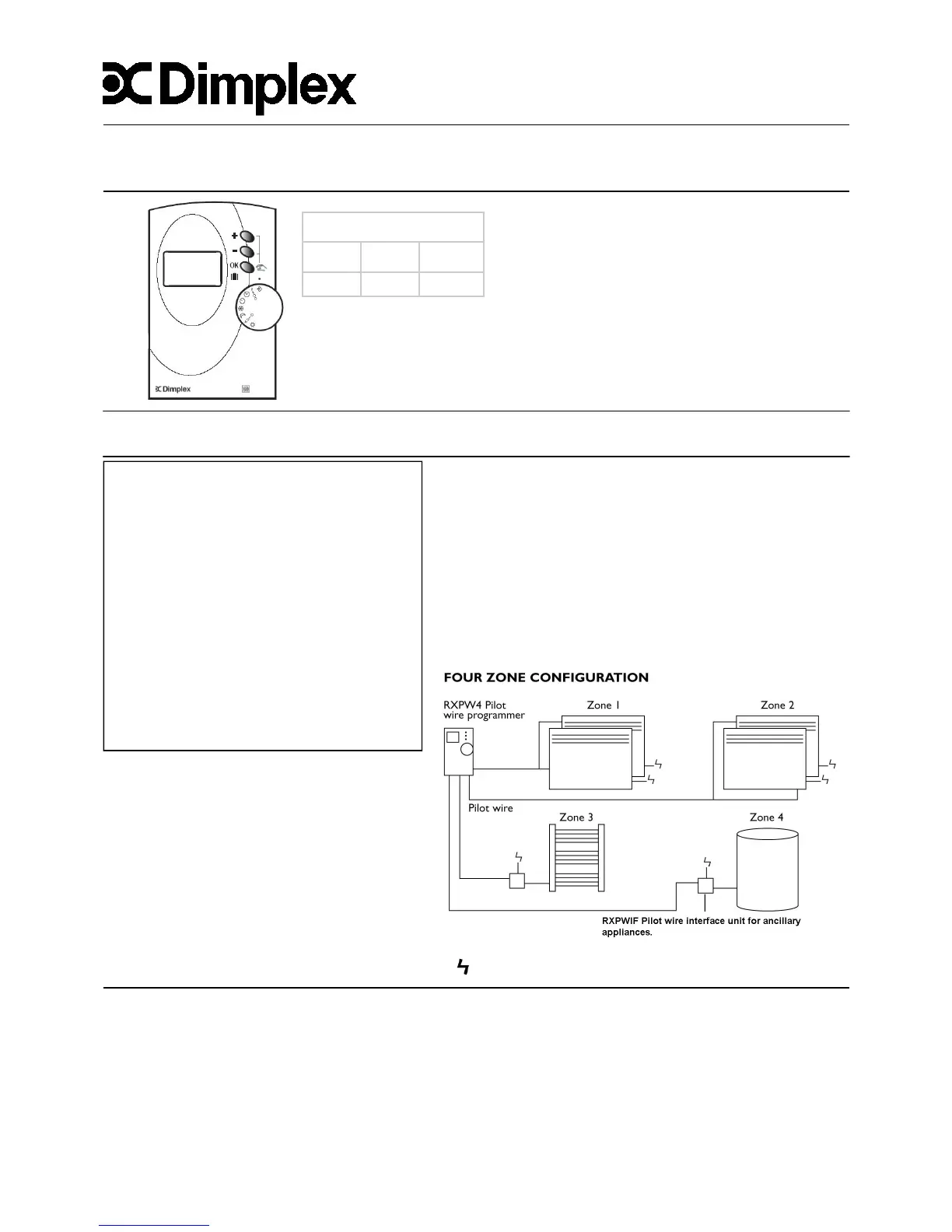
4 Zone Wall Mounted Pilot Wire Controller
Model No. RXPW4
Height Width Depth
120 85 31
Dimensions (mm)
IMPORTANT SAFETY ADVICE
WARNING—This product must be installed
by a competent person or electrician in
conjunction with the current IEE Wiring
Regulations and relevant Building
Regulations
DO NOT cover or obstruct the air inlet
or air outlet vents
DO NOT recess the unit in to a wall,
as this will cause overheating and
potentially be a fire risk
DO NOT install the unit in the
immediate vicinity of a bathroom or
swimming pool
General Principle
The RXPW4 controller is compatible with Dimplex DuoHeat, EPX, Monterey,
Girona, EVS, RPX and Apollo heaters.
The RXPW4 controller is designed to allow control of multiple Dimplex heaters
from a single point.
Each heater contains a mains cable with a fourth black pilot wire which can be
connected to heaters in a system in series.
The controller uses the pilot wire to conduct a 240V, low current signal to each
heater to change the heater mode (e.g. comfort, background or on, off)
Only one programmer is required for up to 20 heaters on the same zone. (See
Fig.1 below)
Fig.1
Technical Specification
Installation in an environment with normal pollution levels
Power supply - 230V~AC, +/- 10%, 50Hz
Functioning temperature - 0 to +40ºC
Storage temperature - -10ºC to 70ºC
Type of disconnection: micro-switching / 1.C type according to EN 60730-1
Clock back up in case of power failure - 4 hours (approx.) Capacitor
Consumption—2VA
Class - II
Protection - IP30
August 2011 - Issue 4
THESE INSTRUCTIONS SHOULD BE READ AND RETAINED FOR FUTURE USE
Pilot Wire Connection
IMPORTANT
Do NOT connect the pilot wire to earth
Care should be taken with the installation of the pilot wire(s)
as when switching to background (setback) they become
energised at 240V although only at a current of 1mA.
In every case a suitable means of isolation must be
provided for the pilot wire and marked to indicate that two
sources of supply may be present at the heater.
Where pilot wires are installed separately from the heater
final sub-circuit they should be protected, double insulated
and carry their own integral earth continuity conductor.
Note: Pilot wire installations are appropriate for single
phase connection only
= 240V domestic supply circuit