452115.66.39 · FD 9707 EN-3
Smart-RTC+ English
3 Scope of supply
3.1 RTM Econ U
Scope of supply:
RTM Econ U for flush mounting
2 screws for fixing into the flush mount box
Installation and operating instructions
3.2 RTM Econ A
Scope of supply:
RTM Econ A for surface mounting
2 screws and 2 dowels for wall mounting
Installation and operating instructions
1 screw for connector cover
4Assembly
4.1 General
The following connections must be made on the RTM Econ A⁄U:
Power supply
BUS line between the heat pump manager and
RTM Econ A⁄U
Control valve control
The RTM Econ A⁄U must not be covered by furniture, wall paper
or anything else. Ensure that the RTM Econ A⁄U is not exposed
to external heating or cooling sources (e.g. draughts in cavity
walls, rising pipes) even on the rear within the flush mount box.
The device must not be installed in areas with direct sunlight or
on an exterior wall, as this could result in incorrect measure-
ments. Observe the recommended installation height of
around 1.5 m above ground. A permissible relative humidity of
max. 90 % must not be exceeded. Operation close to devices
which do not comply with the EMC Directives can also interfere
with the functioning of the device.
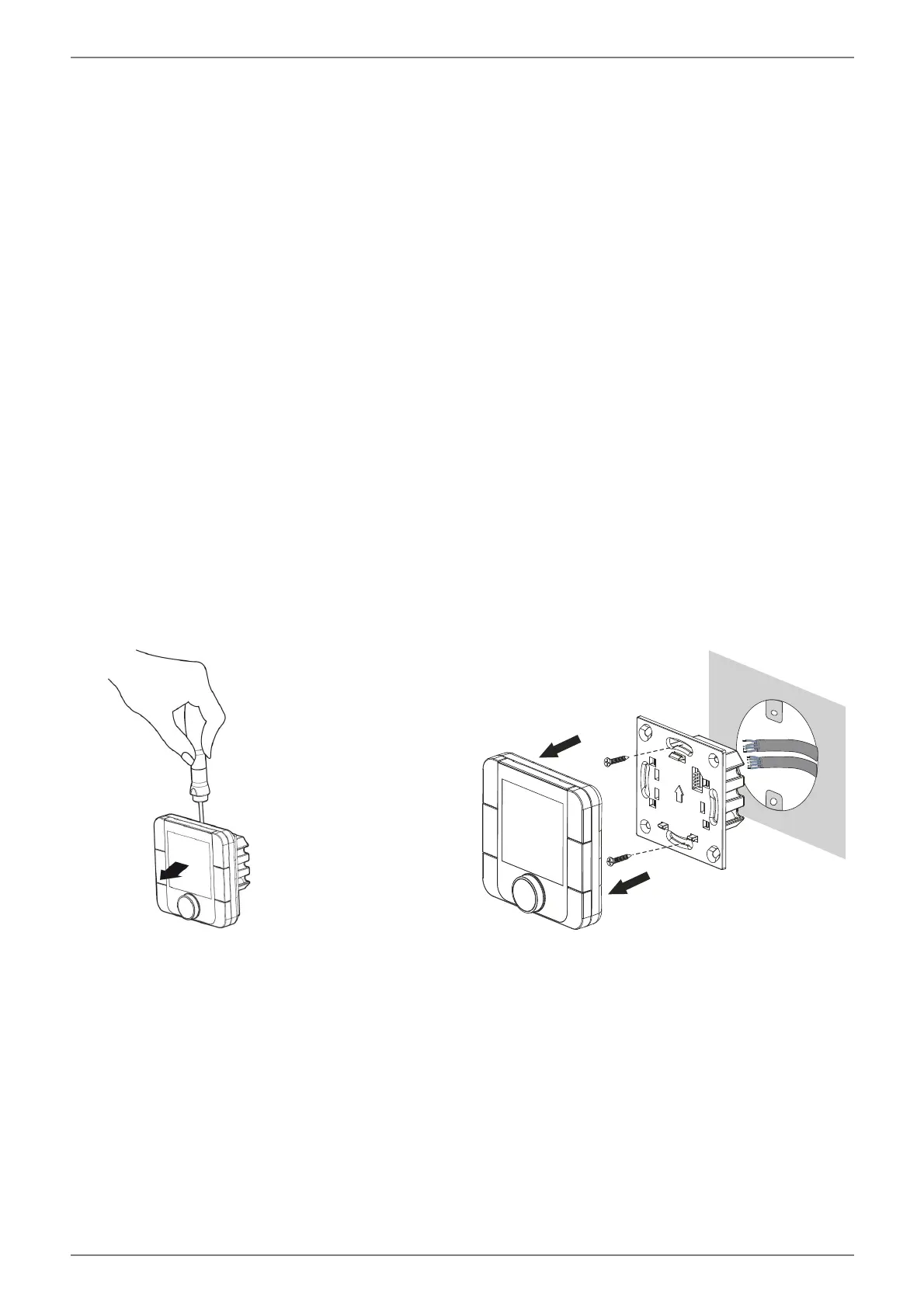
4.2 RTM Econ U
Fig. 4.1:
Fig. 4.2: