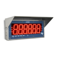
Do you have a question about the Dini Argeo DGT4 and is the answer not in the manual?
Conditions for correct installation of the transmitter and load receiver.
Guidelines for safe and proper electrical connections and installations.
Instructions for correctly earthing load cells, junction boxes, and weighing structures.
Electrical connection diagram for the DGT4 model.
Electrical connection diagram for the DGT4AN model.
Electrical connection diagram for the DGT4PB model.
Electrical connection diagrams for Ethernet-based DGT4 models.
Electrical connection diagram for the DGT4CANOP model.
Electrical connection diagram for the DGT4DEVNET model.
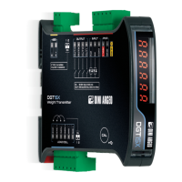
Steps to access the advanced menu and save configuration changes.
Description of key operations within the programming menu.
Continuation of the menu structure with parameter details and cross-references.
Description of the "DEP.CH" mode for connecting load cells.
Description of the "IND.CH" mode for single or multi-cell scales.
Description of the "TRANSM" mode for managing multiple scales.
Theoretical calibration procedure for dependent channels.
Theoretical calibration procedure for independent channels or transm mode.
Calibration using sample weights for dependent channels.
Step-by-step guide for acquiring calibration points with sample weights.
Calibration using sample weights for independent channels or transm mode.
| Brand | Dini Argeo |
|---|---|
| Model | DGT4 |
| Category | Transmitter |
| Language | English |