10 / 16
Typical Compatible
Controller
I/O Extension Modules
ECx-4xx
ECx-4xx
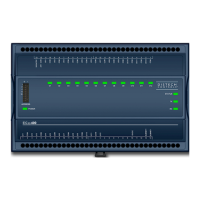
I/O Extension Modules 2 - Wire Shielded
- Last daisy-chained I/O Extension Module:
EOL Jumper is ON
- All other I/O Extension Modules:
EOL Jumpers are OFF
- Last daisy-chained Communicating Sensor:
EOL Jumper is ON
- All other Communicating Sensors:
EOL Jumpers are OFF
Communicating Sensor Sub-Network Bus
- Cat 5e Cable with RJ-45 Connectors
Figure10: Setting the EOL Terminations on the ECx-400 Series Subnetwork Bus when Allure EC-Smart-Vue Sensors are used
ECx-400 Series devices and Allure EC-Smart-Vue sensors are factory-set with the EOL set to OFF by default.
If inserting multiple wires in the terminals, ensure to properly twist wires together prior to inserting them into the terminal connectors.
For more information and detailed explanations on network topology and wire length restrictions, refer to the Network Guide, which can be downloaded
from our website
www.distech-controls.com
. For the UUKL extension module, refer to the Distech Controls UUKL Smoke Control System Design Guide.
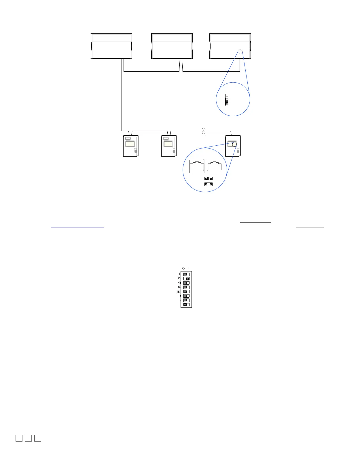
Device Addressing
The Subnet ID Address must be set to one (1) or two (2) by setting the DIP switch located on the faceplate An example of how to set the device’s Subnet
ID Address DIP switch is shown below.
Figure11: Typical I/O Extension Module DIP Switch Set to 2
The address is the sum of the numbers set to ON. For example, if the second (2) DIP switch is set to ON, the I/O Extension Module address is two (2).
Only addresses 1 and 2 are valid.
The I/O Extension Module must be power cycled after the Subnet ID DIP switch has been changed.
 Loading...