7 / 16
Sensor Input Type Input Des-
ignation
Input Connection Diagram
£
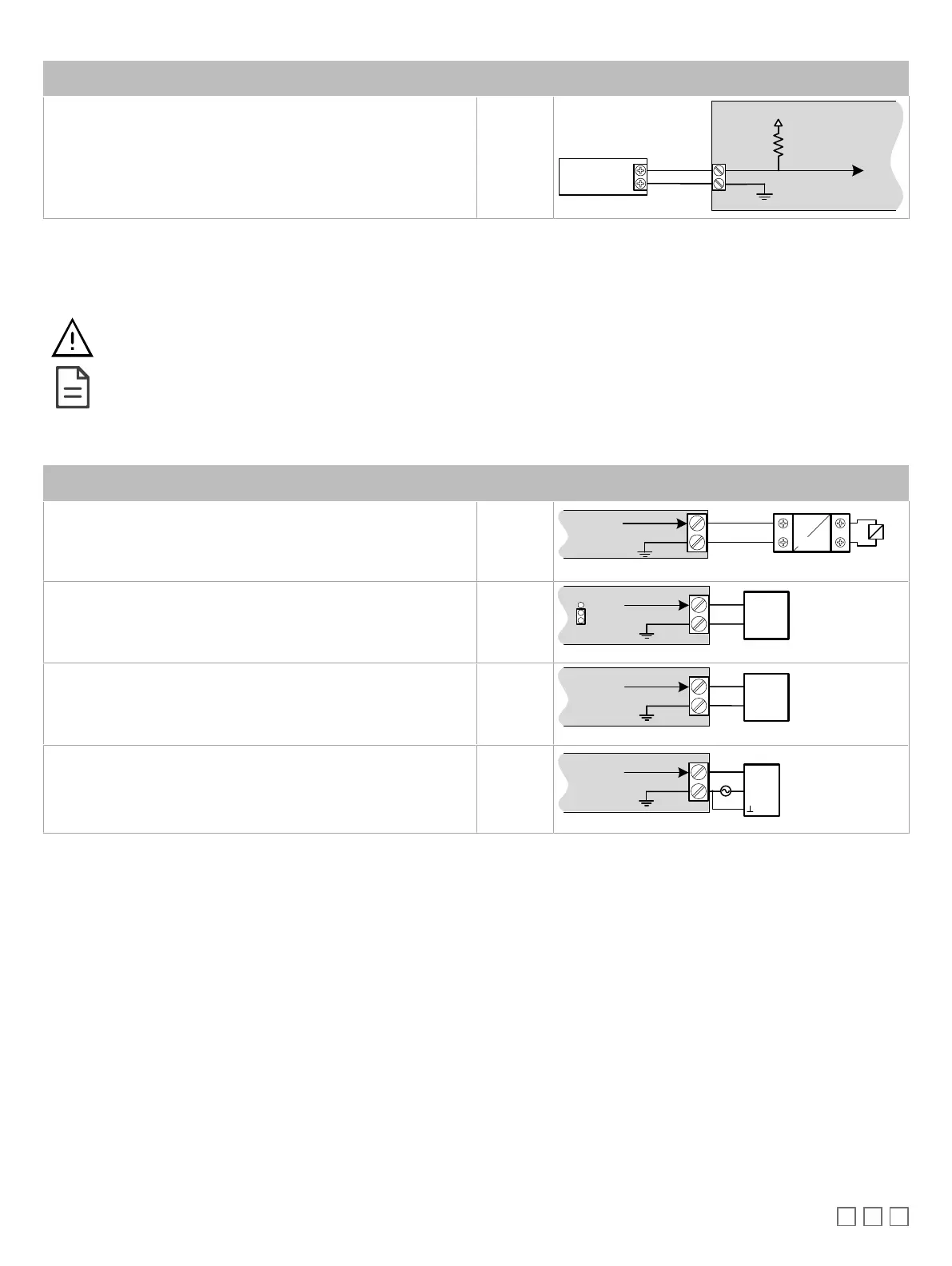
Slow Pulse
–
Internal supply
: 2-wire pulse meter, maximum input fre-
quency of 1Hz (500ms minimum ON/OFF)
£ Connect the pulse input according to the figure for a pulse meter that
can pull-down a +5VDC supply with a 10KΩ pull-up resistor (internal
supply type).
UIx
Pulse Meter
Output
Controller
Pulse Input
Equivalent
Circuit
UIx or DIx
COM
To Pulse Count
Accumulator
+
-
10KΩ
5VDC
Table1: Input Wiring
Output Wiring
Before connecting an output device (actuator, relay, etc.) to the controller, refer to the datasheet and installation
guide of the equipment manufacturer.
£ For a wire length less than 75’ (23m) long, either a shielded or unshielded 18AWG wire may be used.
£ For a wire length up to 200’ (61m) long, a shielded 18AWG wire is recommended.
£ The shield of the wire should be grounded on the controller side and the shield length should be kept as short
as possible.
Table 2 shows the output designation for ECx-400 UUKL I/O Extension Module.
Control Output Type Output
Designation
Output Connection Diagram
£ Discrete 0 or 12VDC digital, Pulse, or PWM output controlling a
12VDC relay.
UOx
From
Digital
Output
12VDC Relay
A1
A2
UOx
COM
£ Current 0 to 20mA universal output & jumper configuration
UOx
0-20mA
Common
From Digital-To-
Analog Output
UOx
COM
JUMPER
SETTING
0-10V
0-20mA
£ Linear 0 to 10VDC digital to analog output.
UOx
0-10V
Common
From Digital-
To-Analog
Output
UOx
COM
£ 0 to 10VDC voltage output controlling an analog actuator that is pow-
ered by an external 24VAC power source.
UOx
0-10V
~ or +
From Digital-
To-Analog
Output
UOx
COM
Actuator
or -
24VAC
Table2: Output Wiring
 Loading...