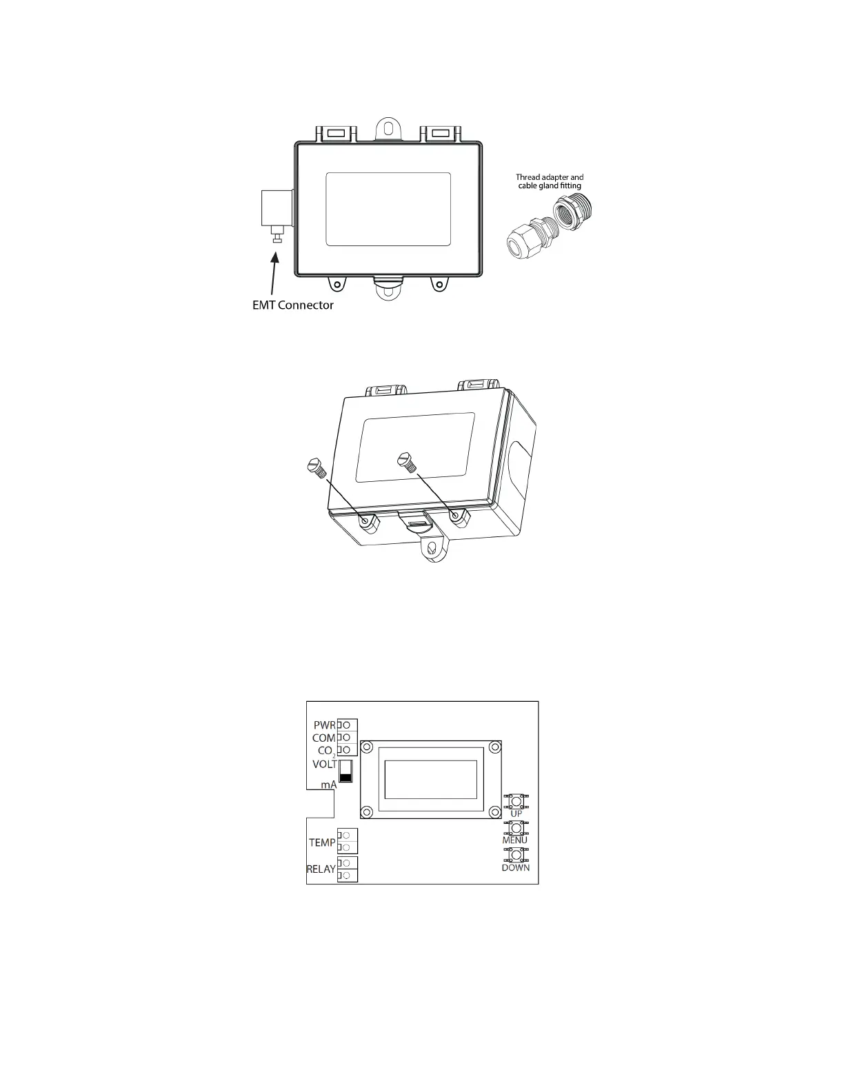
Figure 4. Insert conduit or cable gland
Two security screws are provided which can be installed to help secure the cover once settings and wiring connections are complete.
See Figure 5.
Figure 5. Tighten security screws
Wiring
Deactivate the power supply until all connections are made to the device to prevent electrical shock or equipment damage. Use 16-
22 AWG shielded wire for all connections (only ground the shield at the controller end) and do not locate the device wires in the same
conduit with wiring used to supply inductive loads such as motors. Pull at least six inches of wire into the enclosure and complete the
wiring connection according to the wiring diagram. See Figure 6.
Figure 6. Wiring
This is a 3-wire sourcing device. Connect the plus DC or the AC voltage hot side to the PWR terminal and the common is connected
to the COM terminal. The device is reverse voltage protected and will not operate if connected backwards. It has a half-wave power
supply so the supply common is the same as the signal common. Several devices may be connected to one power supply and the
output signals all share the same common. Use caution when grounding the secondary of a transformer or when wiring multiple
devices to ensure the ground point is the same on all devices and the controller. See Figure 7.
 Loading...