Mounting Instructions
The duct type sensor installs on the outside of a return air duct with the sampling tube inserted into the duct. Use the included foam
plug to prevent air from entering the enclosure through the conduit and causing an incorrect reading.
Mount the sensor in an easily accessible location in a straight section of duct at least five feet from corners or other items that may
cause disturbances in the air flow. Avoid areas where the detector is exposed to vibrations or rapid temperature changes.
The duct CO
2
detector principal of operation is based on the Venturi effect of the probe that extends into the HVAC duct. Air flowing
through the duct is forced into the vent holes on one side of the probe, into the enclosure, over the CO
2
sensor and then is drawn
back out of the enclosure via the probe vent holes on the opposite side.
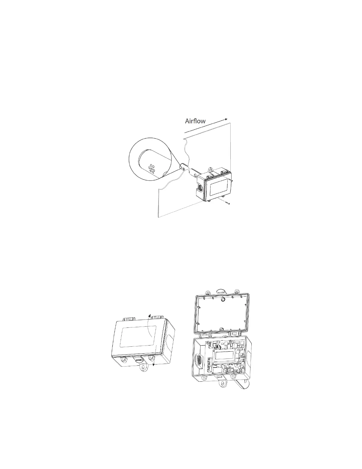
NOTE: To ensure proper temperature readings, if present, the temperature inlet on the probe must be installed directly into the airflow.
See Figure 2.
Figure 2. Mounting the GS-2CDD20K detector
Drill or punch a 7/8” or 1” hole in the duct at the preferred location and insert the probe into the hole to mark the enclosure mounting
holes. Remove the unit and drill the two mounting holes.
Clean all drilled holes of debris before mounting the device. Mount the enclosure to the duct with two sheet metal screws such that
the duct air flow is parallel with the vent holes in the probe (i.e.: air flows directly into the probe holes). To prevent air leaks, ensure
the gasket is compressed around the probe between the device enclosure and the air duct. See Figure 2.
The enclosure has a hinged cover with a latch. Open the cover by pulling slightly on the latch on the bottom of the enclosure, at the
same time pulling on the cover. See Figure 3.
Figure 3. Open hinged cover
A 1/2" NPT threaded connection hole is provided in the side of the enclosure. Screw an EMT connector or cable gland connector in
until tight. A weatherproof conduit or cable gland fitting is recommended. There is an optional 1/2" NPT to M16 thread adapter and
cable gland fitting. See Figure 4.
 Loading...