All aspects of the installation must
conform to requirements of the NEC,
and any applicable local codes.
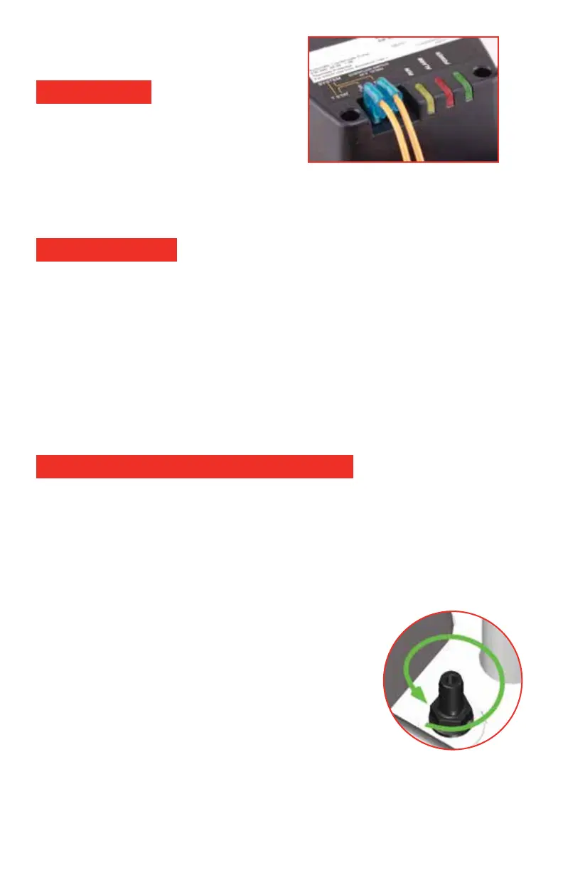
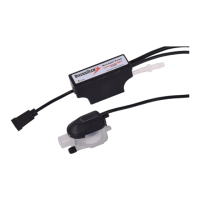
The pump safety switch should be used
on 24V Class II control circuits only. The
pump safety switch connections are
available on standard ¼” quick connect
terminals located on the top cover.
Two wires with pre-crimped connectors may be plugged onto the
COMMON and RUN terminals and wired into the 24 Volt thermostat circuit
to shut o A/C systems should an overow condition occur. The Safety
Switch operates with or without power provided to the pump.
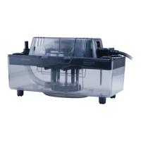
Apply power by plugging in the pump. Check for green LED indication the
power is available. Test oat and safety switch by manually lling the tank
or manually operating the oat. (see disassembly below)
Test Safety Switch operation (if used) to be sure that the A/C system shuts
down and the red ALARM LED lights when the pump has reached an
overow condition.
Leak Check: Operate the pump by lling tank to trigger operation. Pump
RUN will be indicated by the yellow RUN LED.
Homeowner Instruction: Instruct the homeowner about the pump's general
operation and to look for the ALARM LED if they think that there is system
trouble.
Always disconnect power before performing maintenance. Pump and
deck may be removed from the tank by pushing tabs located on the tank
sides away from the deck while liing on the pump cover.
Periodically inspect the Pump tank to assure it is free of accumulated dirt or
sludge. Do not use solvent cleaners. Clean tank with soap and warm
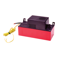
water only. The check valve may be removed for cleaning or replace-
ment by unscrewing with a 9/16 wrench. (illustration)
Clean inlet and outlet piping.
Reassemble system and check for correct operation.
Safety Switch
Pump Operation
Pump Maintenance and Disassembly
DOC32181