Vertical Roof Mounting
NOTE: Roof mounting is recommended as it allows less intake air contaminants and reduces ground-level exhaust.
1. Use furnace installation instructions to determine pipe diameter.
2. Determine correct Extended Concentric Vent size for the pipe diameter selected.
3. Determine the best location for the Extended Concentric Vent.
4. Cut a 4” diameter hole for CVENT-2-EXT, 2” kit.
5. Partially assemble Extended Concentric Vent kit. Follow furnace installation instructions for cleaning and cementing.
a. Cement “Y” tting to larger diameter air inlet pipe (Figure 1).
b. Cement combustion air inlet cap to smaller diameter pipe (Figure 1).
6. Install “Y” tting and pipe assembly through hole and roof boot/ashing (user supplied).
7. Secure to roof (Figure 3) using metal strapping or equivalent support material (user supplied).
8. Install combustion air inlet cap and small diameter pipe assembly into roof. Cement and bottom small diameter pipe in “Y”
concentric tting.
9. Cement furnace combustion air and vent pipes to Extended Concentric Vent. Refer to Figure 3 for proper pipe attachment.
10. Check installation by allowing furnace to run through one cycle.
NOTE: Keep assembly free of insulation during installation.
NOTE: Multiple Extended Concentric Vent kits may be installed vertically following the same clearances between vent outlets as
shown in Figure 6.
NOTE: Termination height must be above roof surface or anticipated snow level (minimum 12” in U.S . or minimum 18” in Canada)
as shown in Figures 2 & 3.
Do not use eld supplied couplings to extend pipes.
CAUTION:
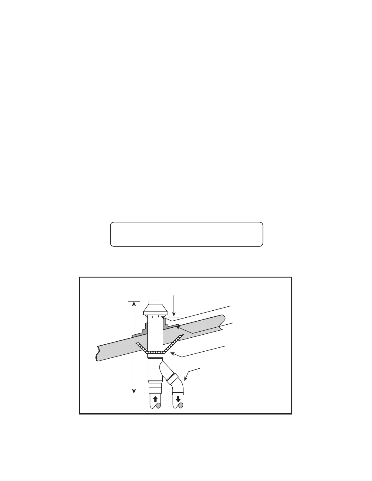
Figure 3–Typical Roof Install
Maintain 12” minimum (18” for Canada) clearance above highest
anticipated snow level. maximum of 24” above roof.
Vent
Combustion Air
Roof weather
Seal/Flashing
(eld supplied)
Combustion Air
Support
(eld supplied)
Elbow
(eld supplied)
Max 60”
 Loading...