Horizontal Sidewall Mounting
NOTE: Refer to the following items before horizontal
installation:
• Check furnace installation instructions for allowable clearances and locations.
• Refer to Figures 4 & 6 when venting multiple units using multiple Extended Concentric Vents.
• Avoid locations with high winds.
• Avoid locations where Extended Concentric Vent is likely to be damaged.
• Avoid locations where vapors are objectionable, or may damage the structure, plants or air conditioning condensing unit.
1. Use furnace installation instructions to determine pipe diameter.
2. Determine correct Extended Concentric Vent size for the pipe diameter selected.
3. Determine the best location for the Extended Concentric Vent.
4. When installing multiple Extended Concentric Vents, refer to the following guidelines:
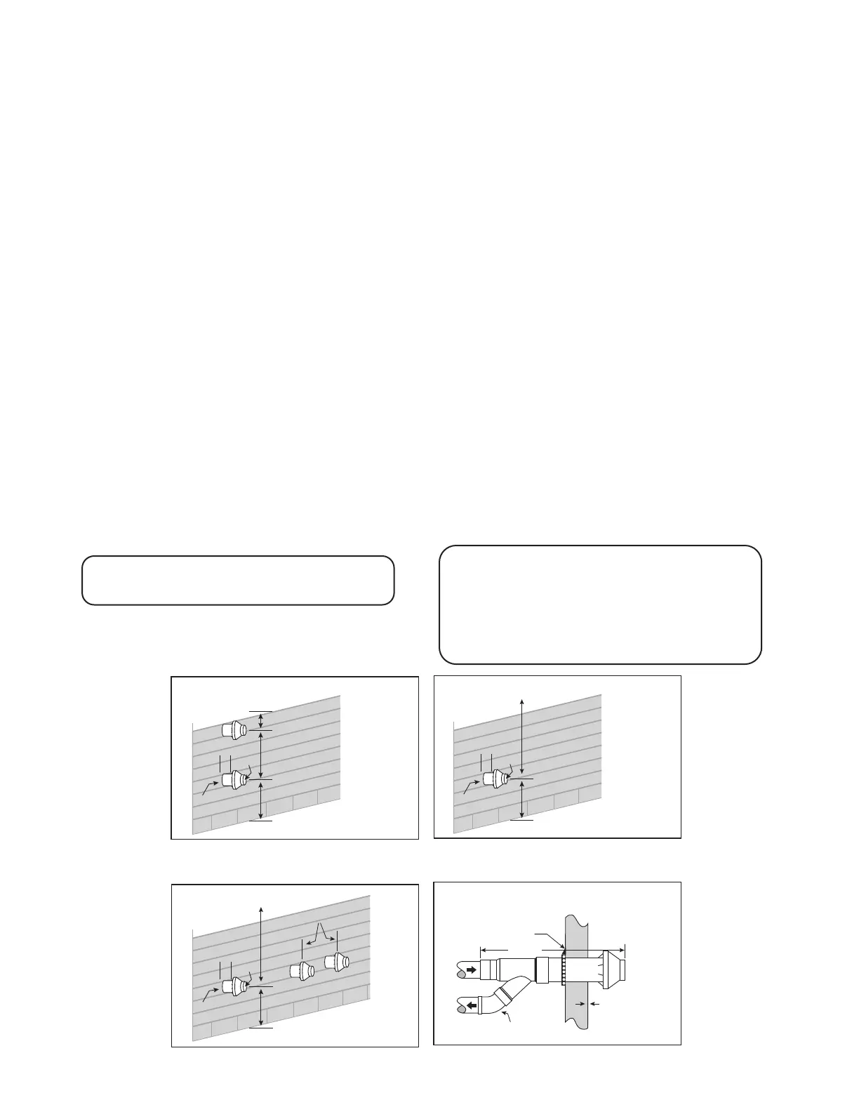
a. Do not install multiple Extended Concentric Vents directly above one another unless separated by a 3’ distance (minimum).
b. Install multiple Extended Concentric Vents where the horizontal distance between the ends of each air intake is 4” or less or
greater than 24”. This will prevent a recirculation of ue gas.
5. Cut a 4” diameter hole for CVENT-2-EXT, 2” kit.
6. Partially assemble the Extended Concentric Vent kit. Follow furnace installation instructions for cleaning and cementing.
a. Cement “Y” tting to larger diameter air inlet pipe (Figure 1).
b. Cement combustion air inlet cap to smaller diameter pipe (Figure 1).
7. Install “Y” tting and pipe assembly through hole.
8. Install combustion air inlet cap and large diameter pipe assembly. Cement and bottom small diameter pipe in “Y” concentric
tting.
9. Secure to structure (Figure 7) using metal strapping or equivalent support material (user supplied).
10. Cement furnace combustion air and vent pipes to Extended Concentric Vent. Refer to Figure 7 for proper pipe attachment.
11. Check installation by allowing furnace to run through one cycle.
Figure 4–Sidewall Termination for Multiple
Vertical Extended Concentric Vents
Figure 7–Sidewall Termination Details
NOTE: Securing strap must be eld installed to prevent
movement to termination kit in side wall
Vent
Combustion air
Strap (eld supplied)
Combustion air
Vent
Elbow
(eld supplied)
1” Combustion
air inlet
vanes to wall
Max 60”
Maintain 12” clearance
abovehighest anticipated
snow level or grade
Combustion air
Vent
Roof Overhang
12” Minimum
36” Minimum
1”
Figure 5–Sidewall Termination
Combustion air
Vent
Roof Overhang
12” Minimum
1”
Maintain 12” clearance
abovehighest anticipated
snow level or grade
Figure 6–Sidewall Termination for Multiple
Horizontal Extended Concentric Vents
Combustion air
Vent
Roof Overhang
12” Minimum
1”
Maintain 12” clearance
above highest anticipated
snow level or grade
Less than 4” or greater than 24”
(between end bell edges)
Do not use eld supplied couplings to extend pipes.
CAUTION:
NOTE: Keep assembly free of insulation during installation.
NOTE: Maintain clearance dimensions as shown in Figure 4, 5, 6 & 7.
Recirculation of ue gasses may occur, causing the
intake pipe to freeze shut during cold weather
operation if the venting system is not installed per
these guidelines. If the venting system is not installed
properly, ue gas may recirculate, possibly causing
the intake pipe to freeze shut during cold weather.
WARNING:
 Loading...