PUSH
TO
TEST
PUSH
TO
RESET
WET
SWITCH
®
Flood
Detector
AUX CONTACTS:
5A 250V
D
I
V
E
R
S
I
T
E
C
H
C
O
R
P
O
R
A
T
I
O
N
•
D
U
L
U
T
H
,
G
A
C
O
N
F
O
R
M
S
T
O
U
L
S
T
D
5
0
8
M
O
D
E
L
N
O
.
W
S
-
1
POWER ON MOISTURE
CLASS II CIRCUIT
2.0 AMPS
Wet Switch prevents ooding and property damage by detecting
moisture caused by accumulation of air-conditioning condensate, drain
leaks, etc. When moisture is detected, the normally closed circuit
controlling the system is disconnected. An additional circuit is included,
normally open, that may be used to operate an alarm device as well.
Multiple Wet Switches may be connected in series (within the electrical
limits of the power supply), to expand coverage area. Wet Switch
incorporates isolated relay contacts, for added exibility in installations
with electronic control boards where breaking one lead from the
transformer is not possible.
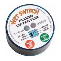
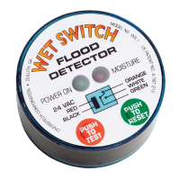
Status Indications & Operation
Normal State: When power is applied and no moisture is
detected, the “POWER ON” LED will be lit green, and the
“MOISTURE” LED will be OFF.
Pressing the red “TEST” button simulates moisture detection and
conrms proper function of Wet Switch. “MOISTURE” LED will be lit
red, & “POWER” LED will be OFF.
Press the green “RESET” button to return Wet Switch to normal state.
When moisture is detected, the control circuit is opened, and the
“MOISTURE” LED is lit red. Wet Switch will remain in this state until the
problem is corrected and the “RESET” button is pressed, or power is
disconnected. Aer correcting the moisture problem, & with power
disconnected, use a clean, absorbent cloth to thoroughly dry the
sensor pad on the bottom of Wet Switch. Any residual moisture in
the pad may cause a false detection. A warm air device (such as
a hair drier on low heat ONLY) may be used to help dry the pad.
Installation
1. Turn o power to the system.
2. Place Wet Switch, padded side down, on the surface to be monitored.
3. Connect wiring as shown in the diagrams on page 2. Wires may be
extended as necessary, but avoid excess run lengths.
4. Restore power to the system.
5. Press “TEST” to assure proper function.
Controlling Selected Components
System components such as compressors, electric valves, condenser
pumps, chill water pumps, or other 24 VAC controls may be connected
selectively and independently to Wet Switch.
Model No. WS-1
WET SWITCH
®
FLOOD DETECTOR
LED Indicators
Wet Switch
Schematic
TEST & RESET
Buttons