Dual Mini Synthesizer Build Instructions
7
Install Power Connector
Insert P3 into the board, aligning the notch in the connector with the notch
indicated on the silkscreen pattern. Make sure the connector is at against the
board, then solder it into place. The pins are short enough that they don’t
need to be trimmed.
Page 2/4
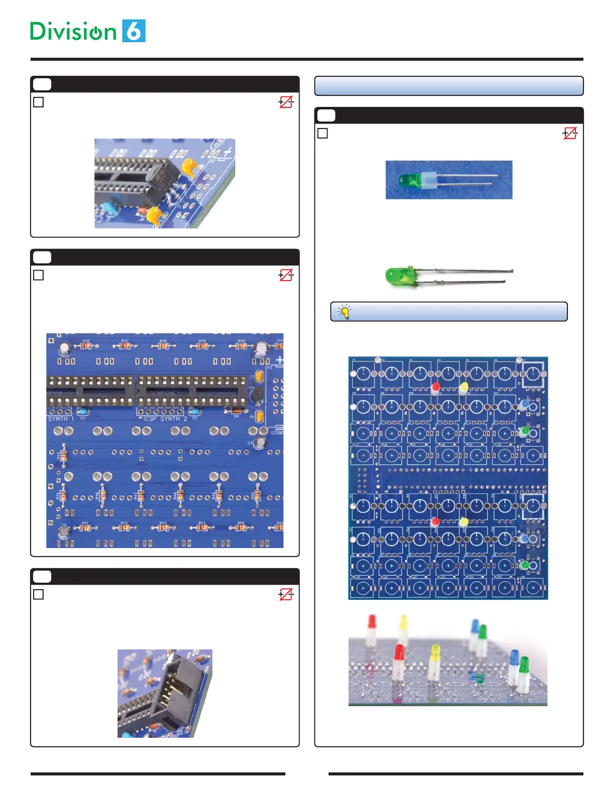
6
Install Electrolytic Capacitors
Insert C1, C2, C7, and C8 into the board. Polarity does matter for electrolyt-
ics, so make sure the (-) stripe is lined up with the - (round) hole on the PCB
(and is opposite the “+” marking on the silkscreen pattern). Solder the
capacitors into place and trim the leads.
5
Install Regulator
Insert VR1 into the board, making sure the at side of the part is lined up with
the at side on the silkscreen pattern. Solder and trim the leads.
Flip the board over! From here on out, all the parts go on the other side
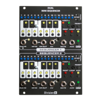
8
Install LEDs
Slip an LED spacer onto each LED D1-8.
Insert the LEDs into the PCB and bend the pins outward to hold the LEDs into
place. Polarity does matter for LEDs; you’ll notice that they all have a at
side on their package. If the at side is hard to see, each LED also has a long
and a short pin to indicate polarity.
FLAT SIDE = SHORT PIN = NEGATIVE (-) = SQUARE PAD ON PCB
It doesn’t really matter which color you put where, but the LEDs in your kit
were chosen with the following layout in mind:
You may want to temporarily t the front panel in place to make sure all the
LEDs are straight and line up with the LED holes in the panel. Solder and trim
the leads.