Do you have a question about the dixell ichill IC260L and is the answer not in the manual?
Importance of reading the manual for correct product usage and reference.
Essential safety measures for installation, operation, and maintenance of the instrument.
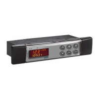
Overview of the controller's primary functions for chiller unit applications.
Detailed table comparing features across different IC200L models.
Explanation of the meaning and function of LEDs on the instrument's key buttons.
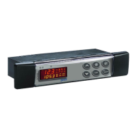
Detailed explanation of the function of each key on the instrument's control panel.
Guide to understanding various icons and their meanings displayed on the instrument.
Detailed explanation of the function and meaning of LEDs on the bottom display.
General steps for initial installation of the instrument.
Step-by-step guide for configuring the Real-Time Clock (RTC) parameters.
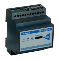
Overview of hardware resources and terminal blocks for IC260L/IC280L models.
Details on connecting NTC and PTC probes to analog input terminals for temperature sensing.
Wiring instructions for connecting a 4-20mA pressure transducer to analog inputs.
Instructions for connecting the Hot Key for parameter upload/download.
Configuration options for analog inputs PB1, PB2, PB7, PB8, PB9, and PB10.
Configuration options for digital inputs ID1 through ID18.
Configuration options for digital outputs (relays) RL1 through RL14.
Comprehensive list of all configurable parameters with their descriptions and ranges.
Guide to navigating programming levels and modifying parameters via the keyboard.
Guide on how to access and navigate through the three programming levels.
Instructions for changing the password for each programming level.
How to select and enable the Chiller or Heat Pump operating mode.
Configuration and conditions for automatic changeover between Chiller and Heat Pump modes.
Instructions for starting, stopping, and entering standby mode via keyboard or digital input.
Procedure to display measurement labels and swap between circuit information.
Setting default read-outs for top and bottom displays for custom views.
How to display and modify the current set point value for chiller or heat pump mode.
Accessing the function menu via the 'M' key for various operations.
Accessing and resetting the alarm list from the function menu.
Procedure for resetting compressor overload alarms.
Activating energy saving mode via a digital input.
Configuring daily time tables for energy saving using the RTC function.
Description of parameters related to compressor thermoregulation for chiller and heat pump.
Configuration for condenser fan speed control modes and parameters.
Configuration for ON/OFF step regulation of the condenser fan.
Conditions and steps required for the defrost cycle to initiate.
Initiating a forced defrost cycle based on specific conditions and time delays.
Detailed steps for the automatic defrost cycle operation.
Explanation of parameters that control the defrost cycle.
List and description of probe failure alarm codes.
Information on evaporator flow alarm triggered by a differential pressure switch.
High pressure switch alarms for circuits 1 and 2.
Compressor high pressure alarms for individual compressors.
Procedure for converting automatic alarms to manual alarms based on event count.
Table showing output status for 'A' type alarms and their corresponding output actions.
Specifications and instructions for panel cut-out dimensions for instrument mounting.
Panel cut-out dimensions for VI620/VI820 vertical boards.
Description of terminal blocks, connectors, and wiring guidelines.
Overview of available accessories for the iCHILL unit.
| Brand | dixell |
|---|---|
| Model | ichill IC260L |
| Category | Control Unit |
| Language | English |