Do you have a question about the dixell ichill IC281L and is the answer not in the manual?
Essential guidelines and safety precautions for using the instrument.
Crucial safety measures to follow before and during instrument use.
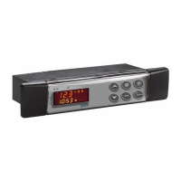
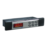
Details the primary functions and management capabilities of the controller.
Describes the meaning and operation of LEDs on the controller's key buttons.
Explains the functionality of each key on the controller's interface.
How to access and navigate through the different programming levels (Pr1, Pr2, Pr3).
Selecting between Chiller and Heat Pump modes via keyboard or digital input.
Instructions for starting, stopping, and entering standby mode from the keyboard.
Using digital inputs to control unit start-up and stop.
Viewing and resetting the alarm list and individual alarms.
Procedure for resetting compressor overload alarms.
Detailed explanation of thermoregulation parameters (ST01-ST11).
Configuration of compressor start-up methods (Direct, Part Winding, Star-Delta).
Pump down function with low pressure switch control.
Pump down function using a dedicated pressure switch.
Pump down function utilizing a dedicated pressure probe.
Configuration for compressor maintenance requests and alerts.
Procedure for initiating a forced defrost cycle.
Description of combined defrost operation using digital inputs.
How to perform a manual defrost.
Step-by-step procedure for automatic defrost operation.
Detailed explanation of each defrost parameter (dF01-dF24).
Details on probe failure alarms and their remedies.
Evaporator flow alarm conditions and reset procedures.
Condenser flow alarm conditions and reset procedures.
Supply fan overload alarm causes and reset.
Evaporator pump overload alarm details.
Condenser/recovery pump overload alarm details.
EEPROM error alarm and its causes.
Power supply frequency alarm conditions.
Generic alarm that stops regulation from a digital input.
Unit configuration alarm codes and their meanings.
Clock failure alarm and its handling.
Clock alarm due to incorrect setting or chip failure.
Unloading alarm due to high evaporator water inlet temperature.
Low ambient air temperature alarm for Air/Air units.
Maintenance requests for evaporator pumps and supply fans.
Maintenance requests for condenser pumps.
High pressure switch alarms for circuits 1 and 2.
Low temperature/pressure alarms for the circuit.
Anti-freeze and low outlet temperature alarms in Chiller mode.
Anti-freeze alarms in Heat Pump mode for Air/Air units.
High pressure/condensing high temperature alarms.
Low pressure switch alarms for circuits 1 or 2.
Low evaporating pressure alarms with pressure transducers.
Condenser fan overload alarms for circuits 1 and 2.
High pressure alarms for compressors 1 through 6.
Pressure switch and oil level alarms for compressors.
High discharge temperature alarms for compressors.
Compressor overload alarms for compressors 1 through 6.
Defrost alarms for circuits 1 and 2.
Unloading disabled alarm due to high condenser temp/pressure in Chiller.
Unloading alarm due to low condenser temp/pressure in Heat Pump.
Recovery disabled alarm due to high condenser temp/pressure in Chiller.
Pump down stop alarm from pressure/low pressure switch.
Pump down alarm during start-up from pressure switch/transducer.
Compressor maintenance request alerts.
Maintenance requests for evaporator pumps and supply fans.
Maintenance requests for condenser pumps.
Output status for 'A' type alarms when corresponding outputs are off.
Output status for 'A' type alarms related to fan and circuit conditions.
Output status for 'A' type alarms affecting compressor outputs.
| Brand | dixell |
|---|---|
| Model | ichill IC281L |
| Category | Control Unit |
| Language | English |