4
switched to “PHONO”, the inputs shall be terminated with the supplied termination plugs (as
factory-inserted at delivery).
15. USB connector. Connect to a computer with the included USB cable to use as an audio interface.
Audio from computer will be sent to CH5 of the mixer. The audio signal from Record output (9) will
be sent to computer.
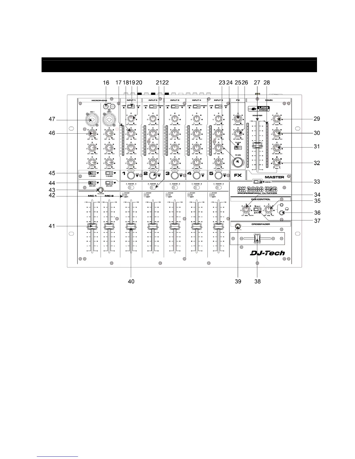
PART NAME AND FUNCTIONS (Top Panel)
16. AUX input. The RCA AUX input for Channel 1.
17. Input level meter for stereo channels. Display the current input level after the Gain control (20) and
allows visual adjustment to the same level for all inputs.
18. Equalizer for stereo channels. Allows the adjustment of the tonal balance for each of the stereo
inputs in three music-specific frequency bands with an adjustment range of -26/+12dB, thus
providing a virtual “kill” function for each frequency band if set to extreme attenuation.
19. Input selector for stereo channels. Switches between the inputs as indicated on the front panel. A
LED indicates the pressed position.
20. Gain control for stereo channels. Allows adjustment of the input sensitivity to compensate for
different source volumes.
21. PFL switch for stereo channels. Assigns the respective channel to the headphone bus for
pre-fader-listening (PFL). A LED indicates the pressed position.
22. Crossfader assignment switch. This switch determines whether the respective channel’s signal is
sent to the left side (A) of the crossfader, the right side (B) of the crossfader or directly to the
master output (MASTER).
23. Effects on/off switch. Activates the effect from FX Return (11). Once the effect is active, this switch
is backlit.