EasyManua.ls Logo

DMC AFM8 - User Manual

DMC AFM8
2 pages
Print Icon
To Next Page IconTo Next Page
Loading...











  

 
 



 

 

 


 
 

  
�SAFETY CLIP









 
   



Question and Answer IconNeed help?

Do you have a question about the DMC AFM8 and is the answer not in the manual?

Summary

General Information

Installation of Positioner

Tool Open Position Requirement

Ensures the tool is in the open position before starting positioner installation.

Safety Clip Removal

Remove the safety clip from the positioner guide before installation.

Positioner Selection

Select the correct positioner for the specific contact to be crimped.

Positioner Insertion and Locking

Insert positioner into guide, push down, and turn 90 degrees to lock bayonet pins.

Wire Size and Selector Knob Setting

Align the wire size number on the dataplate with the selector knob.

Crimping Instructions

Contact and Wire Insertion

Insert contact and prepared wire into the indenter opening of the positioner.

Crimp Cycle Completion

Squeeze handles until ratchet releases; handle returns to open position.

Removing Positioner

Positioner Release Procedure

Push down on positioner to release bayonet pins, turn 90 degrees, and remove.

Gaging Instructions

Go Gage Procedure

Insert GO gage end into closed tool; it must pass freely between indenter tips.

No-Go Gage Procedure

Insert NO-GO gage end into closed tool; it must not pass completely through.

Care of Tool

Maintenance Recommendations

Keep indenter tips free of debris using a small wire brush.

Prohibited Cleaning Methods

Do not immerse tools in cleaning solutions or spray oil for lubrication.

Repair Prohibition

Do not attempt to disassemble the tool or perform unauthorized repairs.

Limitation of Liability

Manufacturer Liability Disclaimer

Corporation not liable for consequential/special damages from product use/misuse.

Limited Warranty

Product Warranty Coverage

Warrants products free from defects for 90 days; correction/refund for defective items.

Overview

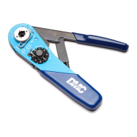
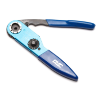
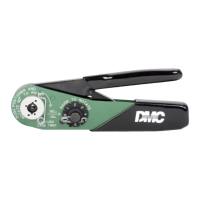
This document describes the Miniature Adjustable Crimp Tool AFM8 (M22520/2-01), a precision hand crimp tool manufactured by Daniels Manufacturing Corporation (DMC).

Function Description

The AFM8 is designed for crimping electrical contacts onto wires. It features a double-action ratchet mechanism, which ensures that the crimping cycle is completed once initiated, preventing partial crimps. The tool is used in conjunction with specific positioners, referred to as 'K' series positioners, which guide the contact and wire during the crimping process. The tool's adjustability allows for precise crimping across a range of wire sizes by selecting the appropriate setting on the selector knob.

Important Technical Specifications

  • Designation: AFM8 (M22520/2-01) refers to the basic tool without a positioner.
  • Wire Crimp Range: The tool is capable of crimping wires from 20 to 32 AWG (American Wire Gauge).
  • Ratchet Mechanism: Features a double-action ratchet that prevents opening the tool until the crimping cycle is complete.
  • Gaging: The tool's crimp quality can be verified using "GO" and "NO-GO" gaging procedures with an inspection gage (e.g., G125 (M22520/3-1) for selector #8). The gaging limits for various selector numbers (1-8) are provided, indicating the acceptable diameter range for the crimped contact. For instance, at selector #1, the "GO" gage diameter is .0130 ±.0001, and the "NO-GO" gage diameter is .0180 ±.0001. At selector #8, the "GO" gage diameter is .0390 ±.0001, and the "NO-GO" gage diameter is .0440 ±.0001.
  • Compliance: This hand tool must not be used in any powered "press" as defined by OSHA CFR 1910.211 (46).

Usage Features

Installation of Positioner:

  1. Ensure the tool is in the open position.
  2. Remove the safety clip from the positioner guide.
  3. Select the correct positioner that corresponds to the contact being crimped.
  4. Insert the positioner into the positioner guide. Push it down and rotate it 90 degrees until the bayonet pins lock securely.
  5. Refer to the tool's dataplate for the correct wire size and corresponding selector number.
  6. With the tool in the open position, remove the spring clip, then raise and rotate the selector knob until the number indicated on the dataplate for the wire size to be crimped aligns with the "Sel. No." arrow.

Crimping Instructions:

  1. Insert the contact and the prepared wire through the indenter opening into the positioner.
  2. Squeeze the handles together until the ratchet releases. The handles will then return to the open position, indicating a completed crimp.

Removing Positioner:

  1. Push down on the positioner to release the bayonet pins from the positioner guide.
  2. Rotate the positioner 90 degrees and then remove it from the tool.

Gaging Instructions ("GO" Gaging):

  1. Operate the tool to the fully closed position.
  2. Maintain firm hand pressure on the tool handles.
  3. Insert the "GO" gage end as shown in the diagram. The gage must pass freely between the indenter tips.

Gaging Instructions ("NO-GO" Gaging):

  1. Operate the tool to the fully closed position.
  2. Maintain firm hand pressure on the tool handles.
  3. Attempt to insert the "NO-GO" gage end as shown. The "NO-GO" gage may partially enter the indenter opening but must not pass completely through.
    • Caution: Do not crimp the gage.

Maintenance Features

The AFM8 tool is designed for minimal maintenance.

  • Cleaning: There is virtually no maintenance required. However, it is good practice to keep the indenter tips free of residual deposits and other debris. A small wire brush may be used for this purpose.
  • Recommended Practices (DO NOT):
    • DO NOT immerse tools in cleaning solution.
    • DO NOT spray oil into the tool to lubricate.
    • DO NOT attempt to disassemble the tool or make repairs.
  • Professional Services: DMC offers complete refurbishing and recalibrating services. As a precision hand crimp tool, it should be handled with care. DMC also engineers and manufactures complete tool kits for various customer requirements, including total aircraft support, general shop maintenance, and on-board ship and vehicle service.

Warranty and Liability

Limited Warranty: DMC warrants each new product to be free from defects in material and workmanship under normal use and service for ninety (90) days after delivery to the first user. The obligation under this warranty is limited to the free correction or refund of the purchase price of any defective product, provided it is returned to DMC with transportation charges prepaid and found defective upon inspection. This warranty does not cover damage caused by normal wear, misuse, improper operation, tampering, neglect, or accident. This warranty is in lieu of all other express or implied warranties.

Limitation of Liability: DMC is not liable for consequential or special damages resulting from the use or misuse of its products. Owners and users of DMC products assume full responsibility for instructing their employees in the proper and safe use of such products.

DMC AFM8 Specifications

General IconGeneral
BrandDMC
ModelAFM8
CategoryCrimp tool
LanguageEnglish

Related product manuals