1165/1165H/1165HS Detectors Installation Sheet Digital Monitoring Products
5
Sensor Reset to Clear LOBAT
When the battery needs to be replaced, a LOBAT message will display on the keypad. Once the battery is replaced, a
sensor reset is required at the system keypad to clear the LOBAT message.
1. On a 7000/9000 Series Keypad, press and hold “2” for two seconds. On a 7800/9800 Series Keypad press Reset
on the carousel menu.
2. Enter your user code if required.
3. The keypad displays SENSORS OFF followed by SENSORS ON.
Battery Life Expectancy
Typical battery life expectancy for DMP wireless smoke detectors is at least 1 year. DMP wireless equipment uses
two-way communication to extend battery life.
The following situations can reduce battery life expectancy:
• If a receiver is unplugged or not installed, transmitters send supervision messages until a receiver returns an
acknowledgement.
• Frequent transmissions, such as how often the detector is tested.
• When installed in extreme hot or cold environments.
The following situation can extend battery life expectancy:
• Extend transmitter supervision time in panel programming.
• Infrequent transmission trips, such as extending the detector test time schedule.
Cleaning the Detector
Clean the detector cover with a dry or damp (water) cloth as
needed to keep it free from dust and dirt. When necessary, clean
the detector interior and replace the smoke chamber as follows:
1. Remove the detector from its mounting base. See
Attaching and Removing the Detector.
2. Remove the batteries. See Replacing the Batteries.
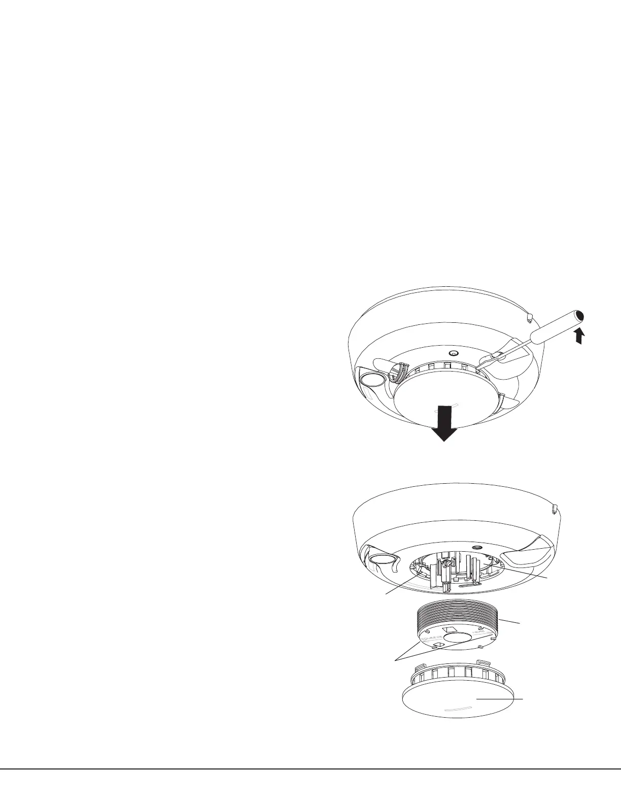
3. Slide a at-blade screwdriver in the slot on the detector
cap and gently push the handle down to pry the cap up
and off. See Figure 6.
4. Press the sides of the smoke chamber in where indicated
by the alignment arrows. Pull the chamber up and away
from the detector and discard. See Figure 7.
Note: The part number of the smoke chamber is UTC211.
5. Blow out or use a soft-bristled brush to remove dust and
dirt from the smoke chamber base.
6. Line the new smoke chamber up with the smoke
chamber base by lining up the arrows on the
smoke chamber to the latches on the optical
base and snap down into place.
7. Replace the detector cap as follows:
— Line the cap up with the smoke detector.
— Insert the cap into the smoke detector and
turn clockwise approximately 15 degrees. It
should snap rmly into place
8. Observing correct polarity, insert two new 3V
lithium batteries into the battery compartment
and replace the cover.
9. Reattach the detector to its mounting base. See
Attaching and Removing the Detector.
10. Test the detector sensitivity. See Testing the
Detector Sensitivity.
Important: The control panel alarm and all auxiliary
functions should be veried for a complete test of the
system.
Figure 6: Remove Detector Cap
Figure 7: Detector Parts
Optical Base
Alignment Arrows
Smoke Chamber
Detector Cap
 Loading...