Green
Input:
120VAC
60 Hz
1.5 Amps
Unswitched
NAC
Module
Battery Wires
(included)
Space for batteries on enclosure lower shelf.
Factory
Installed
Power Limited/class 2 wire
routing through knockouts
into conduit.
Green wire
attaches to
enclosure
mounting
hole.
350 or 350A Enclosure
J6
+ DC -
AC
Trouble
Batt
Trouble
J4
J3J2
Green
LED
AC
AC
+ BAT -
Red
LED
DC
Battery
Start
Gray
Violet
Transformer
Mounting Hole
Mounting
Hole
505-12 Power Supply
NAC
Module
Output
16VAC @ 100VA
12VDC @ 5 Amps
AC and battery output
relay connections
(rated 12V @ 2 Amps)
Red
Black
Black
White
To
AC
Connect Power Supply J4
to a control panel trouble
zone or an 867 NAC
Module trouble zone.
N/C
C
C
N/C
To Panel
To Panel
Optional
wiring
to Panel
Connect NAC modules together.
For Access Control Applications
(UL 294) install the Model 307,
307-S, or 3012 Tamper Switch.
To control panel
tamper zone.
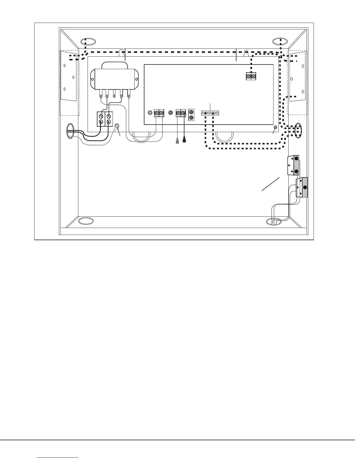
Figure 2: 505-12L and 505-12A Wiring Diagram
Wiring
AC Connection
Connect the transformer to an unswitched 120VAC 60 Hz power source with at least 1.5 Amps of available current.
In Figure 1, connect AC power to the transformer Black and White ying leads. In Figure 2, connect AC power to the
terminal block. Always secure the green wire lead to earth ground.
Note: Use 18 AWG or larger for all power connections. Ensure there is a minimum 0.25" space to keep power limited
wiring separate from non-power limited wiring (120VAC/60 Hz input, battery wires). The power supplies must be
properly grounded before connecting any devices or applying power to the unit. Proper grounding protects against
electrostatic discharge (ESD) that can damage components.
Digital Monitoring Products 505 Series Installation Guide
2
 Loading...