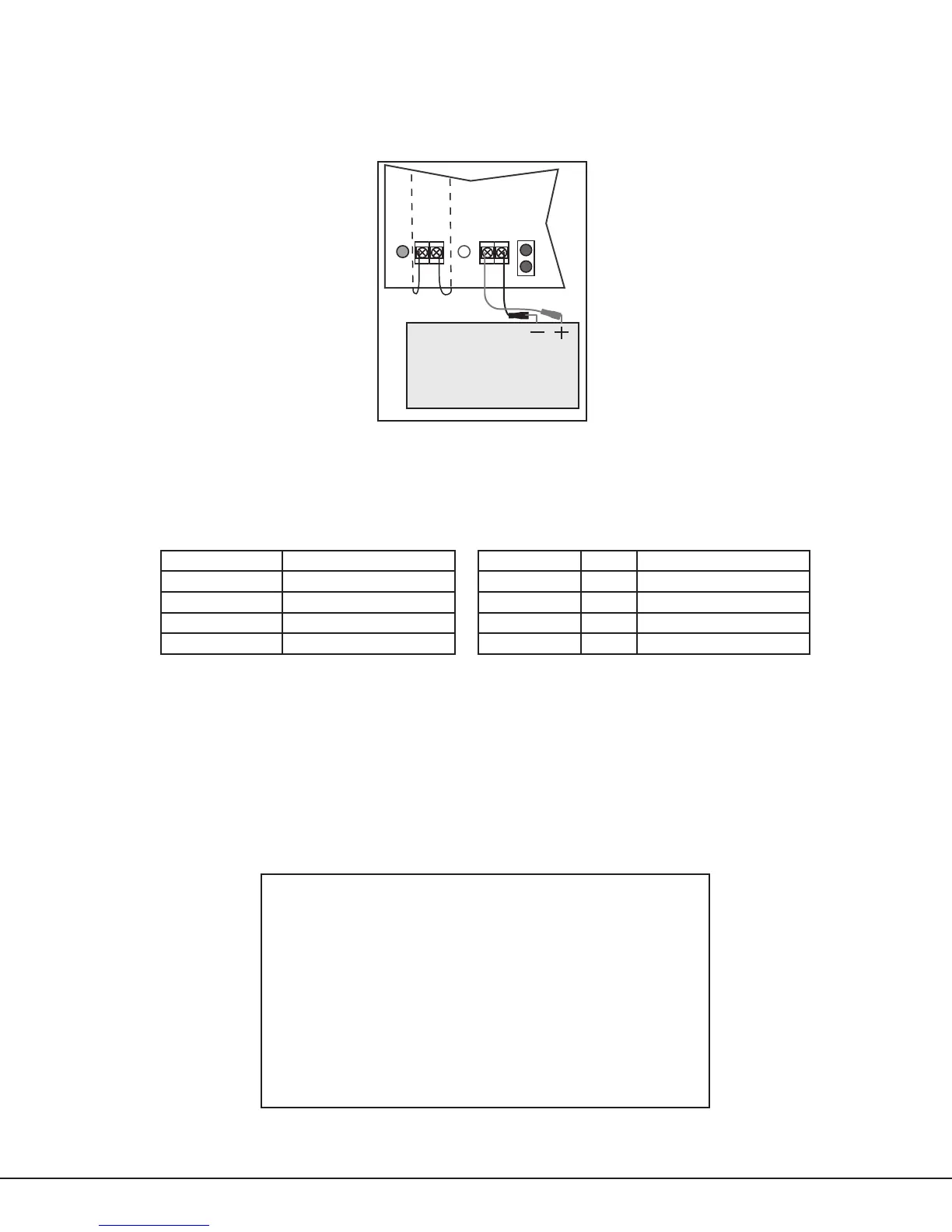
Battery Connection (J3)
Connect the black battery lead to the battery negative terminal. Connect the red battery lead to the positive
battery terminal. Only use sealed lead-acid batteries and replace every 3 to 5 years.
Note: Observe polarity when connecting the battery. Only use sealed lead-acid batteries and replace every 3 to 5
years.
Red
Black
Battery
505-12
J3J2
Green
LED
AC
AC
+ BAT —
Red
LED
DC
Battery
Start
Red
Black
Battery 1
504-24
J3J2
Green
LED
AC
AC
+ BAT —
Red
LED
DC
Battery
Start
Battery 2
Red
Black
Connecting
Strap
Figure 3: Battery Harness Connection
AC and Battery Trouble Relay Connections (J4)
Connect AC TRBL and BATT TRBL supervisory relay outputs marked NC (normally closed) and C (common) to a control
panel or an 867 NAC zone. Relays are form C with the contacts rated at 30VDC. When an AC trouble or Battery trouble
occurs, the relay contacts switch from the NC (normally closed) to the NO (normally open) position. When connected
to a panel, an alarm sounds. When connected to an 867 NAC the LEDs turn off as listed in the table below.
Condition Voltage LED Status Condition
AC Trouble Approximately 102VAC AC LED (GRN) ON AC Good
Battery Trouble Below 11.8VDC AC LED (GRN) OFF AC Bad
Battery Restoral Above 12.4VDC DC LED (RED) ON AC Good, Battery Good
Battery Cutoff Below 10.2VDC DC LED (RED) OFF AC Good, Battery Bad
DC Output (J6)
Connect devices that require power to output terminals marked — DC +.
Note: Measure and verify output voltage before connecting devices to ensure proper equipment operation.
Standby Battery Power Calculations
The following calculation denes the total number of Amp-hours required. From this calculation, assemble the
appropriate number of batteries to slightly exceed the calculated total Amp-hour requirement.
1. Add all standby current values including the power supply operating current.
2. Multiply the total standby current by the number of standby hours needed.
3. Add all alarm current values and multiply by 0.25.
4. Add the total alarm mA-hour with the total standby mA-hour and then multiply this number by 0.001.
Power Supply Operating Current 200 mA
Other Standby Current + _____ mA
1. Total Standby Current = _____ mA
Number of Standby Hours Required x _____ hr
2. Total Standby mA-Hours Required = _____ mA-hr
3. Total alarm current x .25 = _____ mA
(0.25 = 15 minute alarm)
Total Standby Required + _____ mA-hr
Total = _____ mA-hr
x 0.001
4. Total Required Amp-hours = _____
NAC Module Connections
Refer to the panel Installation Guide for information on connecting the various NAC modules to the power supplies.
505 Series Installation Guide Digital Monitoring Products
3
 Loading...