Digital Monitoring Products 734W Installation Guide
2
NO/C/NC (Dry Contact Relay)
The 734W provides a Form C (SPDT) relay for controlling door strikes or magnetic locks. The three relay terminals marked
NO C NC allow you to connect the device wiring to the relay for module control. See Figures 2 and 3 for proper door strike
and magnetic lock wiring.
The Form C relay draws up to 35mA of current and its contacts are rated for 10 Amps (resistive) at 12/24 VDC.
When connecting multiple locks to the Form C relay, the total current for all locks cannot exceed 10 Amps. If the total
current for all locks exceeds 10 Amps, problems may arise and an isolation relay may be needed.
See the Isolation Relay section for information.
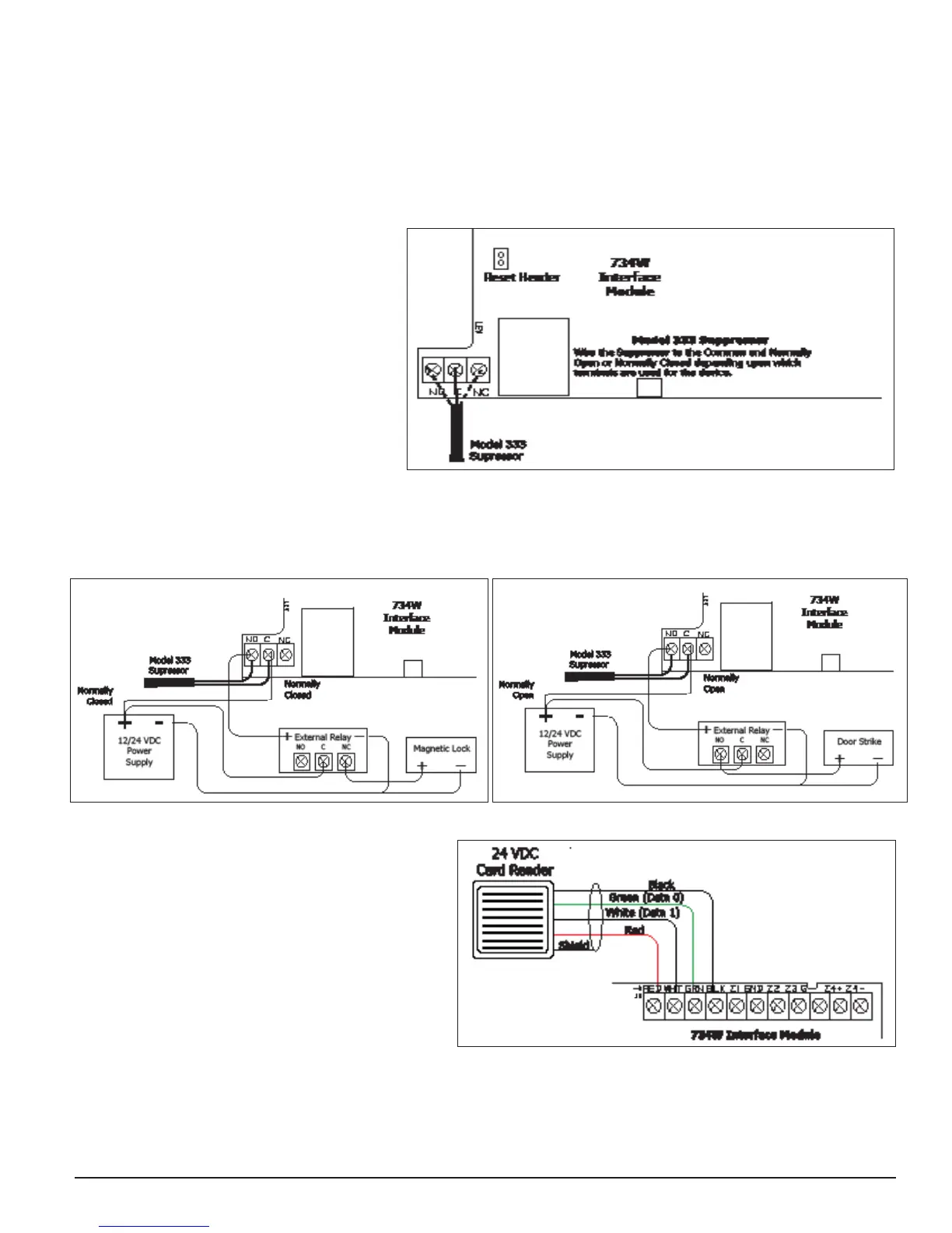
Install the 333 Suppressor
One Model 333 Suppressor is included with
the 734W module. Install the suppressor
across the 734W Common (C) and Normally
Open (NO) or Normally Closed (NC)
terminals.
If the device being controlled by the relay is
connected to the NO and C terminals, install
the suppressor on the NO and C terminals.
Conversely, if the device is connected to
the NC and C terminals, install the 333
Suppressor on NC and C terminals.
The suppressor wire is non-polarized. Install
the suppressor as shown in Figure 4.
Isolation Relay
The Form C Relay can control a device that draws less than 10 Amps of current. If a device draws more than 10 Amp of
current, or the sum of all devices controlled by the Form C Relay exceeds 10 Amps, an isolation relay must be used. Refer to
Figures 5 and 6 for isolation relay wiring.
Connection to Reader
The 734W provides direct 12/24 VDC, 200mA output to
the reader on the J9 Red terminal connection.
Figure 7 shows a reader with wire colors Red, White,
Green, and Black. The wire colors may be different for
the reader being installed. Connect the reader wires to
J9 terminals 1, 2, 3, and 4. As shown in Figure 7, the
Green wire carries D0, or Data Zero, and the White wire
carries D1, or Data One. The Red wire carries 12/24
VDC, 200mA power limited output and the Black wire is
ground.
Status LEDs
The 734W provides two status LEDs. See Figure 1 for locations of the LEDs.
• The Red LED turns on for the duration of the door strike.
• The Yellow LED turns on for one second to indicate a Wiegand read.
• The Green LED is constant to indicate power.
Figure 6: Isolation Relay with Door Strike
Figure 4: Model 333 Installation on the 734W Module
Figure 5: Isolation Relay with Magnetic Lock
Figure 7: Card Reader Wiring
 Loading...