MSEV Series and USHX Hardware Installation Manual Rev 1.7
The reading should be at or near 12VDC, 24VDC, or 24VAC depending on the MSEV
series valve and power source. When supplying 24V, the voltage must be within the
range of 20.4V to 27.6V. When supplying 12V, the voltage must be within the range
of 10.2V to 13.8V.
4. Once the power source output voltage has been identified and checked to be accurate, ensure
that the power supply is off before continuing with the steps below.
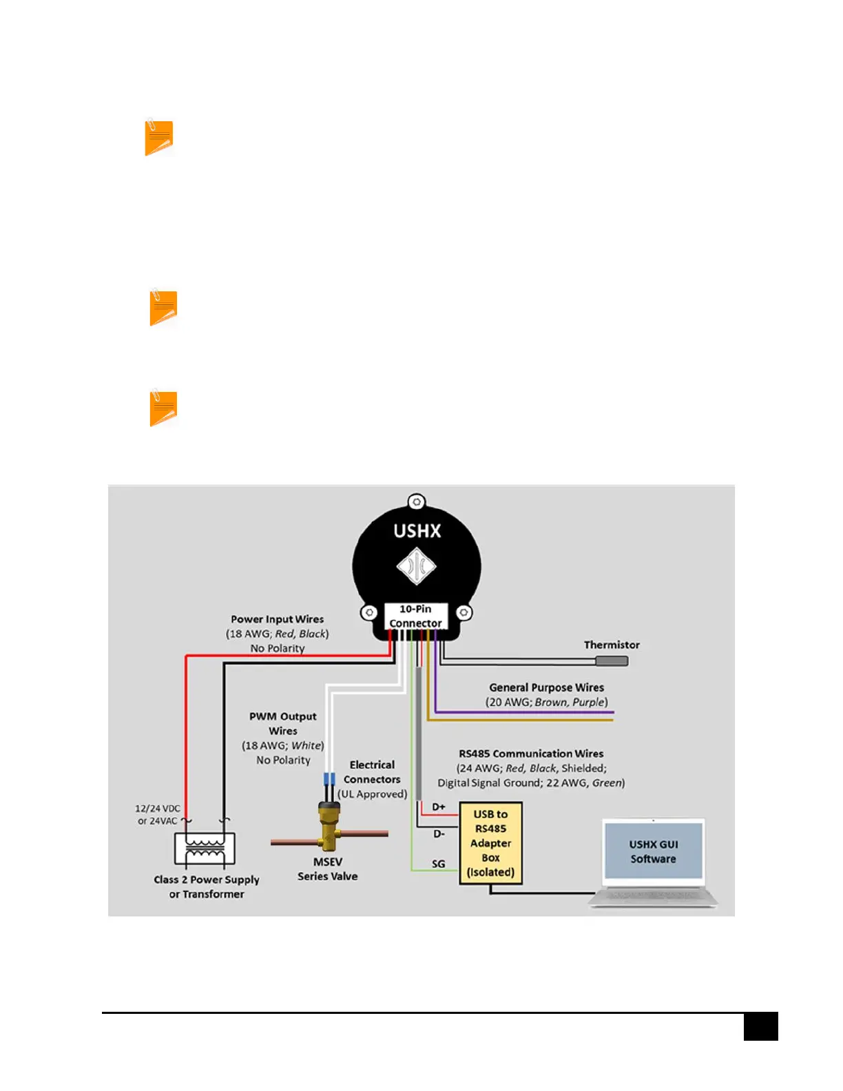
5. The power input wires (18 AWG red/black wires) on the wiring harness should be connected to
the power source as shown below in Figure 3-2.
The USHX power input wires are non-polar, so the wire ordering and colors are not
significant for the purposes of this step in the procedure. All connectors used between
the USHX, power source, and a MSEV series valve should be UL-approved.
The wiring schemes of the ‘Single USHC and MSEV series valve’ and ‘Single USHS Setup’
are the same except that the PWM output wires of the USHS for the ‘Single USHS Setup’
process should be disconnected, terminated with wire nuts, and wrapped with
electrical tape so that they do not form short circuits with each other or any other wires
or metal surfaces. As for the ‘Single USHC and MSEV series valve Setup’ process, the
PWM output wires should be connected to the MSEV series valve as shown below in
Figure 3-2.
Figure 3-2: Single USHC and MSEV series valve wiring diagram