Understanding Leakage Reactance Testing
2-4 72A-2243-01 Rev. B 9/04
September 17, 2004
The common failure modes for a core form transformer are as follows:
• Inward radial hoop buckling
• Outward radial hoop stretching
• Conductor beam bending from generated axial force
• Conductor tilting from cumulative axial force
• Coil end support instability produced by axial force.
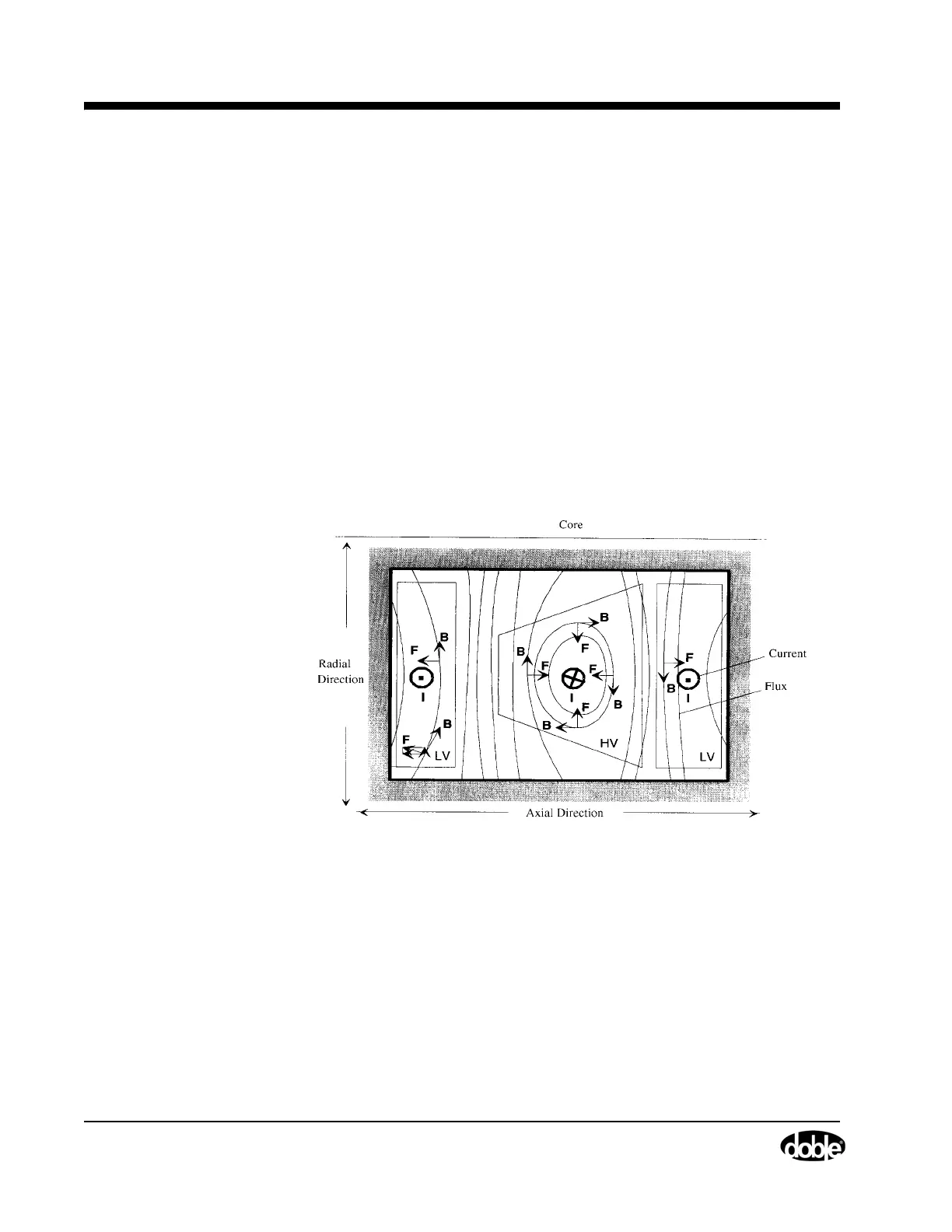
Whereas the principal forces in the core form design were radially directed,
the principal forces in the shell form are axially directed (Figure 2.3). They
tend to separate the low-voltage winding from the high-voltage winding,
which pushes the low-voltage winding against the core. The high-voltage
wincing is being crushed inward upon itself. There are modest radial force
components as well. These tend to compress the pancake winding sections
radially.
Figure 2.3 Generated Forces in a Shell Form Transformer
The common failure modes for a shell form transformer are as follows:
• Conductor tilting from cumulative axial force
• Conductor beam bending from generated axial force
• Radial instability of the winding pancakes
• End support collapse (forces transmitted into the core).
The described windings deformations can affect the leakage flux path, which
in turn may result in the change of the measured leakage reactance.