5 MN1661
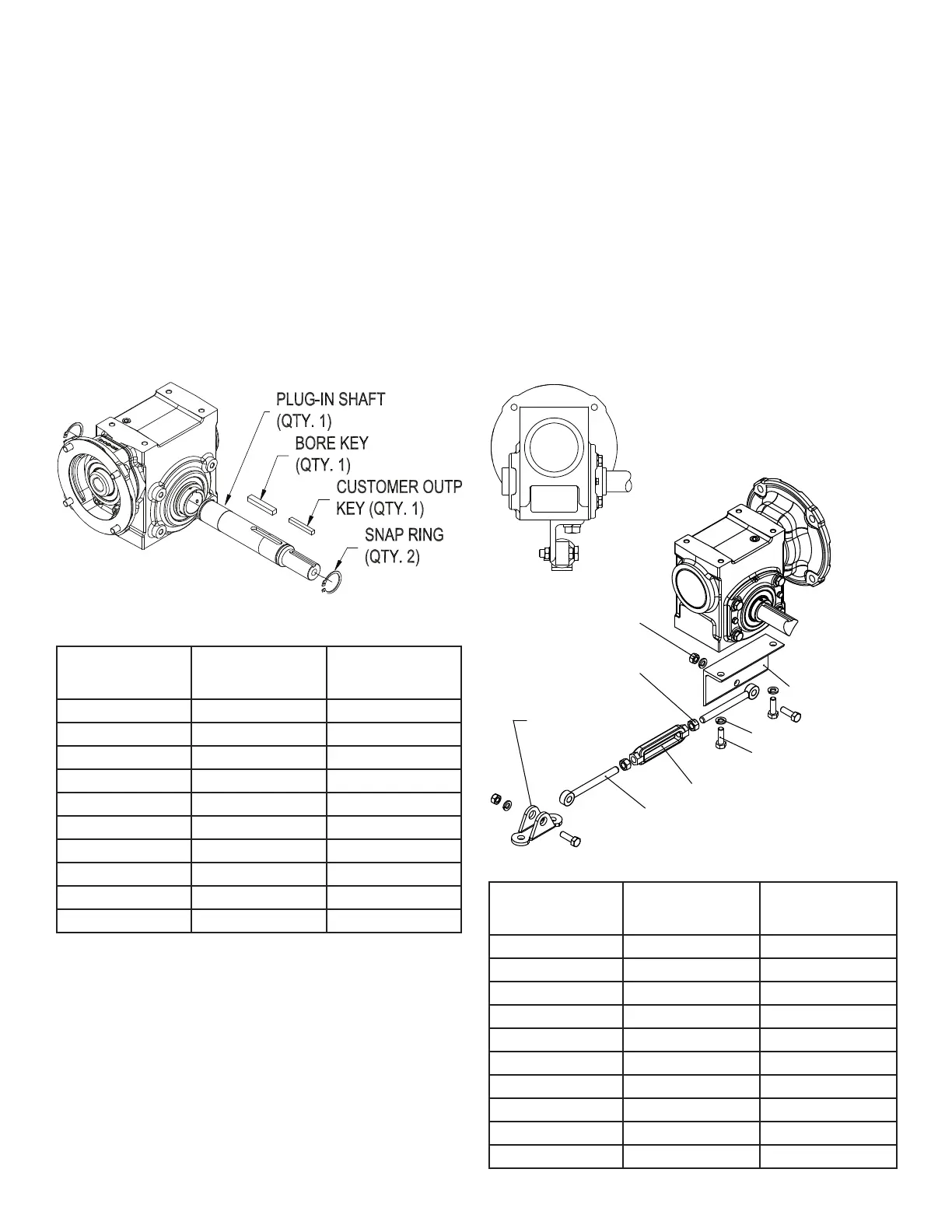
PLUG-IN SHAFT KIT
Install a snap ring on the plug-in shaft near the shaft extension
end. Insert the bore key into the key seat in the plug-in shaft.
Remove the two keyway set screws and loosen the remaining
four set screws in the hollow bore shaft in the reducer. (The
keyway set screws may be used but are not required.) Holding
the plug-in output shaft extension, slide the plug-in shaft into
the hollow bore. Install the second snap ring into the groove in
the plug-in shaft on the non-drive end. Hand tighten one of the
four set screws and then hand tighten a set screw in the same
position on the opposite side of the reducer. Continue to alternate
tightening the set screws until all four set screws have been hand
tightened. After all the set screws have been hand tightened,
use a torque wrench to tighten the set screws to the values in the
table below.
NOTE: Apply a thread-locking compound to the raised diameters
on the plug-in shaft before inserting into the reducer for improved
performance.
Reducer
Size
Bolt or Screw Size
Tightening
Torque
(ft-lb)
13 1/4-28 8
15 1/4-28 8
17 1/4-28 8
20 1/4-28 8
23 1/4-28 8
26 1/4-28 8
30 5/16-24 15
35 5/16-24 15
40 3/8-24 28
47 3/8-24 28
TIE ROD KIT
Assemble tie rod assembly components—right-hand threaded
rod end, right-hand nut, turn buckle, left-hand threaded rod end
and left-hand nut. The tie rod mounting bracket can be located
on the top or bottom of the reducer. Using the diagram below
as a reference, position the bracket so the tie rod assembly
is on the side of the reducer closet the driven equipment.
Install the mounting bracket cap screws and lock washers and
rod assembly onto the mounting bracket and the fulcrum onto
the tie rod assembly using the supplied hardware (cap screws,
lock washers and nuts). Hardware should only be hand-tight.
Install the fulcrum at an angle not more than 30 degrees from the
motor centerline using customer supplied hardware. The tie rod
assembly length can be adjusted by rotating the tie rod assembly
turn buckle. Tighten the tie rod assembly mounting hardware.
Tighten tie rod assembly jam nuts against the turn buckle to lock
the assembly’s length.
Reducer
Size
Bolt or Screw Size
Tightening
Torque
(ft-lb)
13 1/4-20 8
15 1/4-20 8
17 5/16-18 17
20 3/8-16 30
23 3/8-16 30
26 3/8-16 30
30 7/16-14 48
35 7/16-14 48
40 5/8-11 130
47 5/8-11 130
MOUNTING BRACKET (QTY. 1)
THREADED ROD END (QTY. 2)
TURNBUCKLE (QTY. 1)
FULCRUM (QTY. 1)
JAM NUT (QTY. 2)
HEX HEAD CAP SCREW (QTY. 4)
LOCKWASHER (QTY 4)
NUT (QTY. 2)
 Loading...