6 MN1661
MOTOR ADAPTER KIT
Locate the reducer on a secure surface with the input shaft facing
up. Loosen the set screws in both coupling halves. Position the
input shaft. Insert the reducer key and tighten the set screw(s).
Coupling hubs may contain one or two set screws. Rotate the
coupling hub one complete revolution to verify the number of set
screws. Torque all set screws per Table 2 below. A hex socket
and extension, not a T-handle wrench, must be used to tighten
the set screws. Install the o-ring on the motor adapter and install
the motor adapter on the reducer using the motor adapter bolts
and copper washers. Tighten the motor adapter bolts to the
torque values listed in Table 1 below. Install the gasket between
gasket, place and align the gasket onto the motor face for the 56
and 140TC frame motors and onto the motor adapter face for the
180, 210, and 250TC frame motors. A small amount of grease
or other suitable product can be placed on the gasket in three
locations to temporarily hold gasket into place.
NOTE: On 210 and 250 frame motor adapter kits, an adapter plate
and additional gasket may be supplied. Place the adapter plate
onto the gasket on the motor adapter and then place the additional
gasket onto the adapter plate.
Insert the elastomeric element into the reducer coupling half.
Place the motor coupling half onto the elastomeric element.
Install the motor key into the motor shaft. Stake the key into
the motor shaft keyway using a punch or small chisel. Align the
motor shaft key with the coupling half keyway and slowly lower
or the adapter plate face. No visible gap should be present.
Do not use the motor mounting bolts to pull the motor onto
the motor adapter. Install the motor mounting bolts and lock
washers. Torque the motor mounting bolts per Table 3 below.
Looking through the access hole, verify that the coupling faces
are in full contact with the coupling elastomeric element. To
set the required gap, insert a .010–.030” shim or feeler gauge
between the elastomeric element and the motor coupling half.
failure. Tighten the motor coupling set screw(s). Coupling hubs
may contain one or two set screws. Rotate the coupling hub one
complete revolution to verify the number of set screws. Torque all
set screws per Table 2 below. Install access hole plug.
NOTE: The Tigear-2 three piece couplings are sourced from
two manufacturers. Tigear-2 reducers may contain either
manufacturer’s coupling.
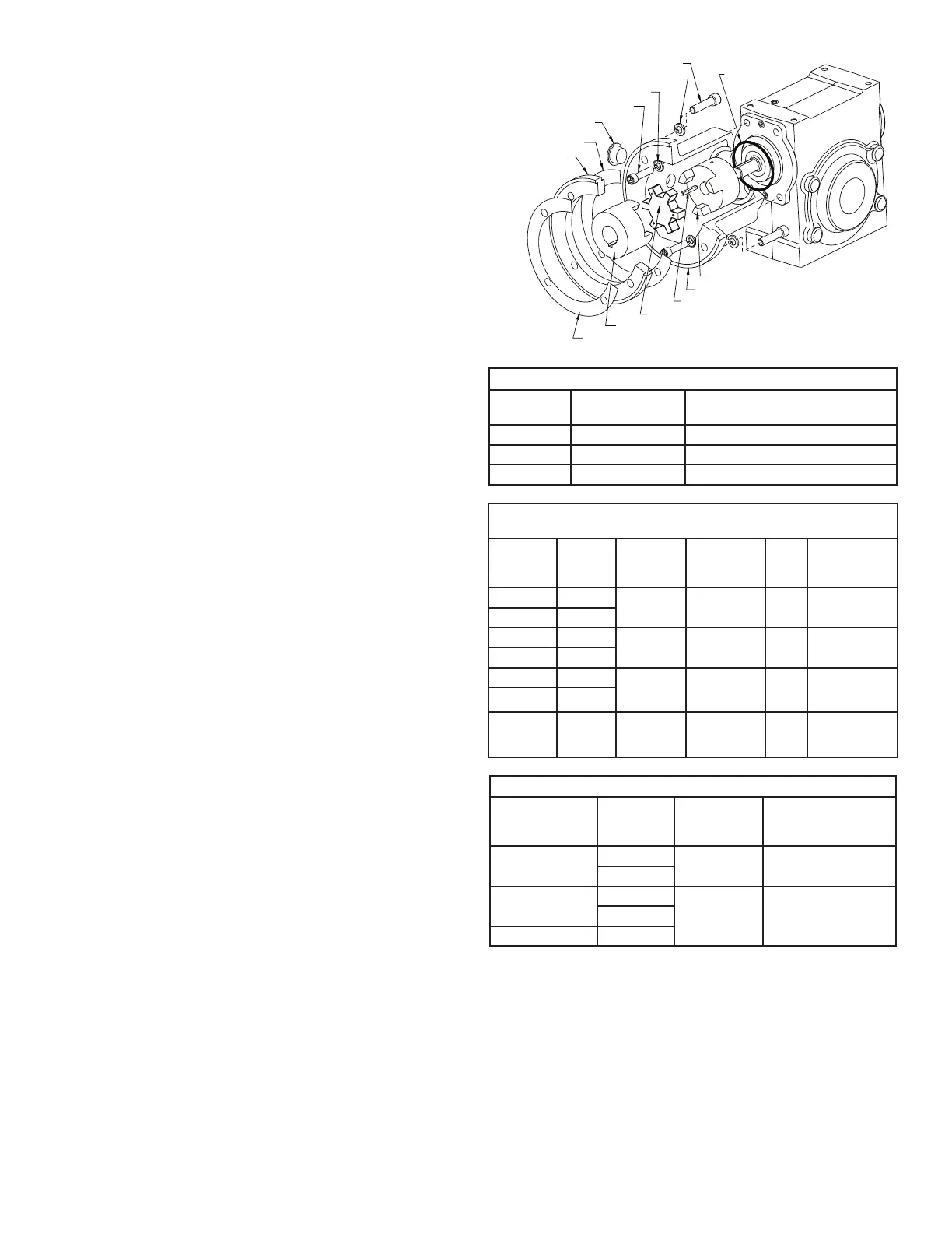
O-RING (QTY.1)
MOTOR ATTACHMENT BOLTS (QTY.4)
LOCKWASHER (QTY.4)
ACCESS PLUG (QTY.1)
GASKET (QTY.1)
ADAPTER PLATE
(QTY.1 - SEE TEXT)
GASKET (QTY.1 -SEE TEXT)
MOTOR COUPLING HALF (QTY.1)
ELASTOMERIC ELEMENT (QTY.1)
MOTOR ADAPTER BOLT (QTY.4)
REDUCER COUPLING HALF (QTY.1)
LOCKWASHER (QTY.4)
MOTOR ADAPTER (QTY.1)
REDUCER KEY (QTY.1)
Motor Adapter Kit Table 1–Motor Adapter Bolt Torque
Reducer
Size
Bolt or
Capscrew Size
Tightening Torque
(non-lubricated)
13 - 20 5/16 - 18 17 ft-lb
23 - 30 3/8 - 16 30 ft-lb
35 - 47 7/16 - 14 48 ft-lb
Motor Adpater Kit Table 2–Three Piece Coupling Motor &
Reducer Coupling Set Screw Torque
Reducer
Size
C-Face
Coupling
Size
Set Screw
Size
Hex
Key
Size
Tightening
Torque
13A - 30A 56C
L075 1/4-20 x 5/16 1/8
78 - 87 in-lb
(6.5 - 7.3 ft-lb)
13A - 15A 140TC
35A 56C
L090 1/4-20 x 5/16 1/8
78 - 87 in-lb
(6.5 - 7.3 ft-lb)
17A - 35A 140TC
40A - 47A 140TC
L099 5/16-18 x 3/8 5/32
150 - 165 in-lb
(12.5 - 13.8
ft-lb)
23A - 47A 180TC
35A - 47A 210TC L110 3/8-16 x 1/2 3/16
260 - 290 in-lb
(21.7 - 24.2
ft-lb)
Table 3–Motor Mounting Bolt Torque
Reducer Size C-Face
Bolt or
Capscrew
Size
Tightening Torque
(non lubricated)
13 - 40 56C 3/8 -16 23 ft-lb
140TC
23 - 47 180TC 1/2 - 13 57 ft-lb
210TC
250TC
 Loading...