Do you have a question about the Dodge Tigear-2 and is the answer not in the manual?
Steps for installing the detachable base onto the reducer's mounting surface, including screw tightening.
Table detailing screw sizes and tightening torques for the bolt-on base kit based on reducer size.
Instructions for inserting the keyed and straight bore bushings into the reducer's hollow shaft.
Procedure for tightening set screws on the bore shaft and specific torque for the screw over the key.
Guidance on positioning riser blocks between the reducer and base for optimal fit.
Instructions for installing and tightening screws for the riser blocks.
Procedure for attaching the output flange to the bearing cover side of the reducer.
Steps for installing the output flange on the side without a bearing cover.
Instructions for attaching the output bracket to the reducer bottom.
Details on tightening screws and lock washers for the output bracket.
Procedure for installing the safety cover on the bearing cover side.
Steps for installing the safety cover on the side without a bearing cover.
Instructions for positioning and securing the transition base to the reducer.
Steps for attaching the detachable base to the transition base.
Procedure for installing J-mount brackets onto the reducer.
Instructions for securing the reducer using foundation bolts.
Steps for preparing the plug-in shaft and reducer bore.
Guidance on tightening set screws for the plug-in shaft assembly.
Description of tie rod assembly parts and their assembly.
Instructions for mounting the bracket and assembling the fulcrum.
Procedure for setting coupling halves and tightening set screws.
Steps for installing the motor adapter, gasket, and o-ring.
Torque values for motor mounting bolts and coupling set screws.
Instructions for cleaning and assembling the bushing components.
Steps for installing the bushing onto the shaft and tightening the nut.
Procedure for mounting the torque arm bracket on the bearing cover side.
Steps for mounting the torque arm bracket on the non-bearing cover side.
Guidance on attaching the torque arm bracket to the customer's structure.
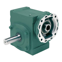
The Tigear-2 Accessory Kit provides a range of components designed to enhance the versatility and functionality of Tigear-2 speed reducers. This kit includes various add-ons such as bolt-on bases, straight bore bushings, riser blocks, output flanges, output brackets, output safety covers, transition kits, J-mount bases, plug-in shafts, tie rods, and motor adapters, each serving specific purposes to adapt the reducer to different application requirements.
The Bolt-On Base Kit allows for the secure mounting of the reducer. The detachable base is installed with its smooth side facing the mounting surface of the reducer. The kit includes screws that must be tightened in a two-step process: first to two-thirds of the specified torque, and then to the final torque value. If washers are provided, their use is critical for proper attachment. This accessory provides a stable foundation for the speed reducer, facilitating its integration into various machinery and systems.
The Straight Bore Bushing Kit is used to adapt the reducer's hollow bore to a straight shaft. Installation involves loosening set screws in the hollow bore, inserting the keyed bushing and key, and aligning clearance holes with set screws. Anti-seize compound is applied to the driven shaft before sliding the reducer on. The set screws are hand-tightened in an alternating pattern to eliminate wobble, then fully tightened with a torque wrench to specified values. This ensures a secure and concentric fit between the reducer and the driven shaft, crucial for smooth power transmission.
Riser blocks are used to adjust the height of the reducer, placing them between the reducer and the bolt-on base. These blocks can be supplied as two pieces with two holes each or as one piece with four holes. If offset holes are present in the two-piece style, the blocks should be positioned to minimize overhang from the reducer. The supplied screws are tightened in a two-step process, similar to the bolt-on base, with washers being essential if provided. A critical warning emphasizes that the supplied pre-coated fasteners, designed for single use, must be replaced if removed during initial installation to prevent serious injury or death from falling items. This kit offers flexibility in mounting height, allowing for better alignment with other machinery components.
The Output Flange Kit provides a means to attach additional components to the reducer's output side. Installation varies depending on whether it's on the bearing cover side or the side without a bearing cover. For the bearing cover side, the four retaining screws on the outside corners of the bearing cover are removed and discarded, while the two smaller screws are kept. The output flange is then installed over the bearing cover using supplied longer screws, flat washers, and lock washers, tightened in a two-step process. For the side without a bearing cover, the output flange is installed with supplied shorter screws, flat washers, and lock washers. This kit expands the reducer's connectivity options, allowing for integration with a wider range of driven equipment.
The Output Bracket Kit is used to attach an output bracket to the bottom of the reducer. The installation involves using supplied screws and lock washers. If a spacer is included, it is placed between the reducer top and the output bracket, utilizing longer bolts. All screws are tightened to the specified torque values. This bracket provides additional mounting points or support for the reducer in specific applications.
Output Safety Covers are designed to protect the hollow shaft units. Installation on the bearing cover side requires removing and discarding the four retaining screws and lock washers on the outside corners of the bearing cover, while keeping the two smaller screws. The safety cover is installed using longer screws, with lock washers sandwiched between two larger flat washers. The drain port must be oriented downwards if possible, and screws are torqued to specified values. For installation on the side without a bearing cover, shorter screws are used, with lock washers sandwiched between two larger flat washers. This accessory enhances safety by covering exposed rotating parts and helps maintain the integrity of the reducer by preventing debris ingress.
The Transition Kit facilitates mounting the reducer to different bases. The transition base is positioned on the reducer with counter-bored holes facing away. Supplied socket head screws and lock washers are used to secure it, tightened to specified torque values. If a detachable base is used, it is then positioned on the transition base and secured with hex head screws. This kit provides adaptability for mounting the reducer to various existing structures or bases.
The J-Mount Base Kit provides a robust mounting solution for the reducer. J-mount brackets are installed on the reducer using supplied screws and lock washers, hand-tightened initially. The reducer is then installed in the application, and foundation bolts are hand-tightened. Finally, the J-mount bolts and lock washers on the reducer are tightened to specified values, followed by the foundation bolts. This kit offers a strong and stable mounting option, particularly useful in applications requiring elevated or specific positional mounting.
The Plug-In Shaft Kit allows for the conversion of the hollow bore reducer into a solid shaft output. A snap ring is installed on the plug-in shaft near the shaft extension end, and a bore key is inserted into its key seat. The two keyway set screws in the hollow bore shaft are removed, and the remaining four set screws are loosened. The plug-in shaft is then slid into the hollow bore, and a second snap ring is installed on the non-drive end. The four set screws are hand-tightened in an alternating pattern, then fully tightened with a torque wrench. A thread-locking compound is recommended on the raised diameters of the plug-in shaft for improved performance. This kit offers flexibility in output configuration, enabling the reducer to drive equipment designed for solid shafts.
The Tie Rod Kit is used to prevent the reducer from rotating about the driven shaft. It consists of right-hand threaded rod ends, right-hand nuts, a turnbuckle, left-hand threaded rod ends, and left-hand nuts. The tie rod mounting bracket can be positioned on the top or bottom of the reducer, preferably on the side closest to the driven equipment. The mounting bracket cap screws and lock washers are tightened to a specified torque. The tie rod assembly is then attached to the mounting bracket and a fulcrum, with hardware hand-tightened. The fulcrum should be installed at an angle not exceeding 30 degrees from the motor centerline using customer-supplied hardware. The length of the tie rod assembly can be adjusted via the turnbuckle, and jam nuts are tightened to lock the assembly. This kit ensures the reducer remains stationary during operation, absorbing torque and preventing unwanted rotation.
The Motor Adapter Kit facilitates the attachment of various motor frames to the reducer. The installation process involves several steps:
This kit is crucial for integrating the speed reducer with a wide range of electric motors, ensuring proper alignment and efficient power transmission. The detailed installation steps and torque specifications are vital for reliable and safe operation.
| Housing Material | Cast Iron |
|---|---|
| Brand | Dodge |
| Series | Tigear-2 |
| Category | Industrial Equipment |
| Type | Worm Gear Reducer |