Solar Pump Inverter Chapter 3 System Collection Diagram
20
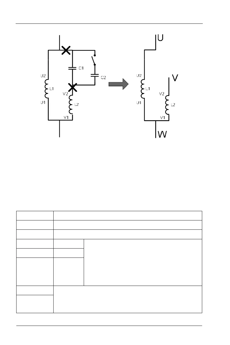
U1 and V1 are common ends of winding to connect with W phase output of solar Pump
inverter, connect U2 end of running winding to U phase output and connect V2 of starting
winding to V phase output.
After adjustment of positive way, change the running direction by F00.13 as same with
positive/negative way control of three phase motor.
3.2.3 Communication terminal description
Terminal name Description
PE Grounding terminal
COM +24V common terminal
DI2 Switch input2
1.Internal impedance:3.3kΩ
2.Acceptable 12~30V voltage input
3.Single-way input terminal, only supports NPN wiring.
4.Maximum input frequency:1kHz
5.Programmable digital input terminal, user can set
terminal functions by function codes.
6.DI1 short circuit
with COM by default internally, no
leading outwards.
DI3 Switch input 3
DI4 Switch input 4
485+
485 communication interface,485 differential signal interface, standard
485 communication port connects in twisted pair cable or shielded
cable.
485-