Solar Pump Inverter Chapter 3 System Collection Diagram
19
3.2.2.2 Terminal 7 is AC output terminal to connect water pump motor. When three phase
motor is used, please connect the U, V, W three phase of the motor to U, V, W of solar
Pump inverter, motor frame connects PE pin of terminal 7.
3.2.2.3 If single phase motor is used, there are two wiring methods according to different
control modes.
(1) Single phase control method: connect the phase wire of single phase motor to U, W of
the inverter terminal 7, motor frame connects PE pin of terminal 7. This method doesn’t
need to disassemble the motor starting capacitor, convenient wiring but bad starting
performance makes that it’s only applicable for some single-phase motors.
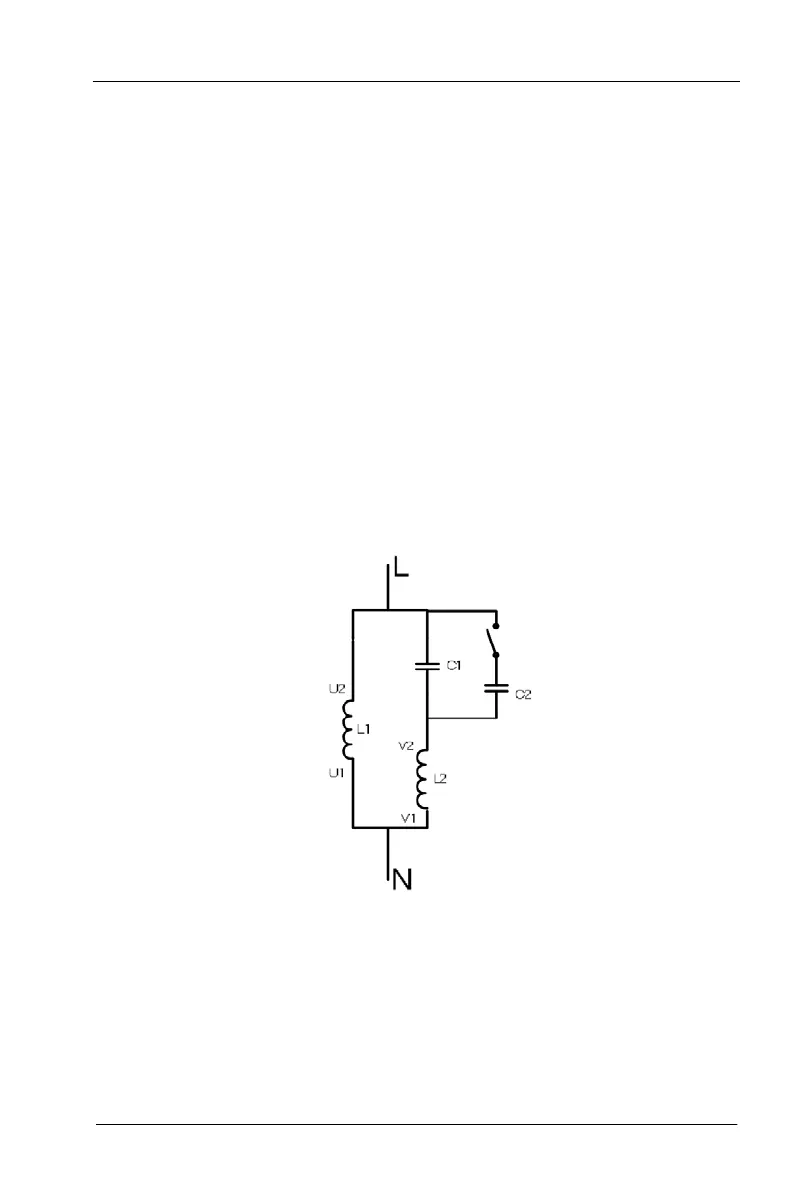
(2) Two phase control method: this method needs to disassemble starting capacitor and
running capacitor (if existed) of the motor. Internal wiring of normal single-phase motor is
as below, L1 is running winding, L2 is starting winding, C1 is running capacitor, C2 is
starting capacitor. When the speed of motor is beyond 75% of rated speed, starting
capacitor breaks off through centrifugal switch.
Disassemble the starting capacitor and running capacitor, internal wiring of single phase
motor winding is as below: