Solar Pump Inverter Chapter 3 System Collection Diagram
18
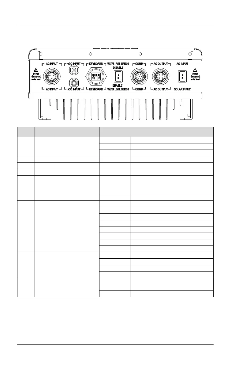
3.2 CT112A Main Circuit Terminals
3.2.1 Terminals description of CT112A
No Terminal name Pin definition
1
AC input terminal
1.L
.
3.PE
PV input terminal: negative
3 PV input terminal: positive +DC INPUT
5 Water level indication switch
1. DI3
Short circuit: water shortage. Direct
short-
circuit running without water
level sensor
6
Functional terminal
1.485+
.
3.DI2 Short circuit: full water
.
Short circuit: water shortage
5.COM
.
7.+24V
.
7
AC output terminal
1.U
.
3.W
.
8 Solar/mains switch
1. DI4
Solar restrict switch,
F05.04=42, DI4 setting
3.2.2 Power terminal description
3.2.2.1 Terminal 1 is AC input terminal, which is involved in the model supports mains input.
Live wire of the grid links with L, neutral wire links with N, earth wire links with PE.
(Attention: make sure PE is connected reliably for safety)