EasyManua.ls Logo

Dometic 3313189.000 C/F-Wht User Manual

Dometic 3313189.000 C/F-Wht
17 pages
To Next Page IconTo Next Page
Page #1 background imageLoading...
Page #1 background image
Read these instructions carefully. These
instructions MUST stay with this product.
USA
SERVICE OFFICE
Dometic Corporation
1120 North Main Street
Elkhart, IN 46514
CANADA
Dometic Corporation
46 Zatonski, Unit 3
Brantford, ON N3T 5L8
CANADA
SERVICE CENTER &
DEALER LOCATIONS
Please Visit:
www.eDometic.com
RECORD THIS INFORMATION FOR FUTURE
REFERENCE:
Model Number
Serial Number
Date Purchased
This Unit is designed for OEM installation. All initial installations must be approved by Dometic Corporation.
Roof Top Unit Used With 3105007.XXX OR 3105935.XXX Return Air Grille
Description Blizzard NXT
TM
Model
Electronic Control Kit Thermostat Optional Indoor
Temperature
Sensor
Air Conditioner
CCC 2 Controls H540315
H540316
3312020.000 3314082.000 CCC 2-Blk
3314082.011 CCC 2-Wht
3311931.000-20′
3311931.012-40′
3311931.020-60′
LCD SZ Controls H540315
H540316
3313189.000 C/F-Wht
3313189.015 C/F-Blk
3313192.000 C/F-Wht
3313192.019 C/F-Blk
N/A
REVISION A
Form No. 3316207.000 09/16
(French 3316208.000_A)
©2016 Dometic Corporation
LaGrange, IN 46761
INSTALLATION
INSTRUCTIONS
Question and Answer IconNeed help?

Do you have a question about the Dometic 3313189.000 C/F-Wht and is the answer not in the manual?

Dometic 3313189.000 C/F-Wht Specifications

General IconGeneral
BrandDometic
Model3313189.000 C/F-Wht
CategoryAir Conditioner
LanguageEnglish

Summary

Important Safety Instructions

General Safety Messages

Provides critical warnings regarding qualified technicians, modifications, and accessories.

Installation Instructions

Choosing Proper Location For Unit

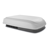
Guides on selecting the optimal roof location considering RV size, heat gain, and tilt.

Roof Preparation

Details essential safety precautions and steps for preparing the roof opening.

Wiring Requirements

Specifies routing for 120 Vac, 12 Vdc, and thermostat communication cables.

Thermostat, Optional Indoor Temperature Sensor & Thermostat Communication Cable Installation

Details the physical installation and connection of thermostats and sensors.

Installing Unit

Covers checking gasket alignment, mounting the unit, and connecting internal wiring.

120 Vac Power Supply Connection

Explains the safe connection of the 120 Vac power supply to the unit's junction box.

System Configuration

Explains how to configure the electronic control via dip switches for optimal operation.

Wiring Diagrams

Related product manuals