Do you have a question about the Dometic 3313192.019 C/F-Blk and is the answer not in the manual?
| Model | 3313192.019 C/F-Blk |
|---|---|
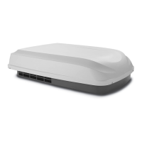
| Type | Roof Top Air Conditioner |
| Color | Black |
| BTU | 13, 500 BTU |
| Cooling Capacity | 13, 500 BTU/h |
| Power Supply | 115V AC |
Provides critical warnings regarding professional installation and product modification.
Instructions for preparing the RV roof opening and ensuring structural integrity.
Details on routing and connecting 120 Vac power, 12 Vdc supply, and communication cables.
Step-by-step instructions for installing thermostat, sensor, and communication cables.
Steps for aligning the unit, attaching it to the roof, and connecting internal components.
Safety precautions and steps for connecting the 120 Vac power supply to the unit.
How to configure the system settings using dip switches for proper operation.
Procedures for resetting the system and performing a post-installation checkout.