1
USAUSA
USAUSA
USA
SERVICE OFFICE
The Dometic Corp.
509 So. Poplar St.
LaGrange, IN 46761
CANADACANADA
CANADACANADA
CANADA
Dometic Dist.
866 Langs Dr.
Cambridge, Ontario
CANADA N3H 2N7
Form No. 3106500.006 3/95
©1995 The Dometic Corp.
LaGrange, IN 46761
RECORD THIS UNIT INFORMATION FOR FUTURE REFERENCE:RECORD THIS UNIT INFORMATION FOR FUTURE REFERENCE:
RECORD THIS UNIT INFORMATION FOR FUTURE REFERENCE:RECORD THIS UNIT INFORMATION FOR FUTURE REFERENCE:
RECORD THIS UNIT INFORMATION FOR FUTURE REFERENCE:
INSTINST
INSTINST
INST
ALLAALLA
ALLAALLA
ALLA
TION & OPERATION & OPERA
TION & OPERATION & OPERA
TION & OPERA
TINGTING
TINGTING
TING
INSTRUCTIONSINSTRUCTIONS
INSTRUCTIONSINSTRUCTIONS
INSTRUCTIONS
Model Number
Serial Number
Date Purchased
®
WW
WW
W
ARNINGARNING
ARNINGARNING
ARNING
Improper installation, ad-Improper installation, ad-
Improper installation, ad-Improper installation, ad-
Improper installation, ad-
justment, alteration, servicejustment, alteration, service
justment, alteration, servicejustment, alteration, service
justment, alteration, service
or maintenance can causeor maintenance can cause
or maintenance can causeor maintenance can cause
or maintenance can cause
injury or property damage.injury or property damage.
injury or property damage.injury or property damage.
injury or property damage.
Refer to this manual. ForRefer to this manual. For
Refer to this manual. ForRefer to this manual. For
Refer to this manual. For
assistance or additionalassistance or additional
assistance or additionalassistance or additional
assistance or additional
information consult a quali-information consult a quali-
information consult a quali-information consult a quali-
information consult a quali-
fied installer or servicefied installer or service
fied installer or servicefied installer or service
fied installer or service
agency.agency.
agency.agency.
agency.
AA
AA
A
VERVER
VERVER
VER
TISSEMENTTISSEMENT
TISSEMENTTISSEMENT
TISSEMENT
Une mauvaise installation, deUne mauvaise installation, de
Une mauvaise installation, deUne mauvaise installation, de
Une mauvaise installation, de
mauvais réglages, modifications oumauvais réglages, modifications ou
mauvais réglages, modifications oumauvais réglages, modifications ou
mauvais réglages, modifications ou
opérations d’entretien peuventopérations d’entretien peuvent
opérations d’entretien peuventopérations d’entretien peuvent
opérations d’entretien peuvent
endommager les biens ou mêmeendommager les biens ou même
endommager les biens ou mêmeendommager les biens ou même
endommager les biens ou même
blesser. Se reporter à la notice. Pourblesser. Se reporter à la notice. Pour
blesser. Se reporter à la notice. Pourblesser. Se reporter à la notice. Pour
blesser. Se reporter à la notice. Pour
obtenir de l’aide ou desobtenir de l’aide ou des
obtenir de l’aide ou desobtenir de l’aide ou des
obtenir de l’aide ou des
reseignements complémentaires,reseignements complémentaires,
reseignements complémentaires,reseignements complémentaires,
reseignements complémentaires,
consulter un installateur qualifié ouconsulter un installateur qualifié ou
consulter un installateur qualifié ouconsulter un installateur qualifié ou
consulter un installateur qualifié ou
une agence de service après-vente.une agence de service après-vente.
une agence de service après-vente.une agence de service après-vente.
une agence de service après-vente.
THIS UNIT IS DESIGNED FOR OEM INSTALLATIONTHIS UNIT IS DESIGNED FOR OEM INSTALLATION
THIS UNIT IS DESIGNED FOR OEM INSTALLATIONTHIS UNIT IS DESIGNED FOR OEM INSTALLATION
THIS UNIT IS DESIGNED FOR OEM INSTALLATION
ALL INITIAL INSTALLATIONS MUST BE APPROVED BY THE SALES DEPT.ALL INITIAL INSTALLATIONS MUST BE APPROVED BY THE SALES DEPT.
ALL INITIAL INSTALLATIONS MUST BE APPROVED BY THE SALES DEPT.ALL INITIAL INSTALLATIONS MUST BE APPROVED BY THE SALES DEPT.
ALL INITIAL INSTALLATIONS MUST BE APPROVED BY THE SALES DEPT.
®
®
CERTIFIED
LR23565
637G
MODELSMODELS
MODELSMODELS
MODELS
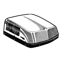
600 Series Penguin600 Series Penguin
600 Series Penguin600 Series Penguin
600 Series Penguin
579 Series BRISK AIR579 Series BRISK AIR
579 Series BRISK AIR579 Series BRISK AIR
579 Series BRISK AIR
590 Series QUICK COOL590 Series QUICK COOL
590 Series QUICK COOL590 Series QUICK COOL
590 Series QUICK COOL
595 Series QUICK COOL595 Series QUICK COOL
595 Series QUICK COOL595 Series QUICK COOL
595 Series QUICK COOL
Roof Roof
Roof Roof
Roof
TT
TT
T
op Air Conditionerop Air Conditioner
op Air Conditionerop Air Conditioner
op Air Conditioner
USED WITHUSED WITH
USED WITHUSED WITH
USED WITH
Part No. 3106481.009Part No. 3106481.009
Part No. 3106481.009Part No. 3106481.009
Part No. 3106481.009
Electronic Kit ControlElectronic Kit Control
Electronic Kit ControlElectronic Kit Control
Electronic Kit Control
57908.52157908.521
57908.52157908.521
57908.521
57912.62157912.621
57912.62157912.621
57912.621
57915.42157915.421
57915.42157915.421
57915.421
57915.42657915.426
57915.42657915.426
57915.426
57915.52157915.521
57915.52157915.521
57915.521
57915.52657915.526
57915.52657915.526
57915.526
57915.62157915.621
57915.62157915.621
57915.621
57915.62657915.626
57915.62657915.626
57915.626
59016.52159016.521
59016.52159016.521
59016.521
59016.52659016.526
59016.52659016.526
59016.526
59016.62159016.621
59016.62159016.621
59016.621
59016.62659016.626
59016.62659016.626
59016.626
59516.50159516.501
59516.50159516.501
59516.501
59516.50659516.506
59516.50659516.506
59516.506
59516.60159516.601
59516.60159516.601
59516.601
59516.60659516.606
59516.60659516.606
59516.606
600312.321600312.321
600312.321600312.321
600312.321
600312.421600312.421
600312.421600312.421
600312.421
600315.321600315.321
600315.321600315.321
600315.321
600315.421600315.421
600315.421600315.421
600315.421