EasyManua.ls Logo

Dometic 57912.531 User Manual

Dometic 57912.531
19 pages
To Next Page IconTo Next Page
Page #1 background imageLoading...
Page #1 background image
INSTALLATION
INSTRUCTIONS
Lire et comprendre ce manuel avant
de procéder à l'installation, à des ré-
glages, de l'entretien ou des parations.
L'installation de cet appareil doit être
effectuée par un réparateur qualié.
Toute modification de cet appareil
peut être extrêmement dangereuse et
entraîner des blessures ou dommages
matériels.
520 Series DUO-THERM HP
530 Series DUO-THERM HP HEAT PUMP
579 Series BRISK AIR
590 Series BRISK AIR
591 Series HEAT PUMP
595 Series QUICK COOL
600 Series PENGUIN
630 Series PENGUIN
Roof Top Air Conditioners & Heat Pumps
Used With Part No. 3109226.005 & 3109407.001
Comfort Control Center Electronic Control Kit
Ducted Installation Using
3109228.001 (White) Comfort Control Center
TM
OR
3109228.019 (Black) Comfort Control Center
TM
THIS UNIT IS DESIGNED FOR OEM INSTALLATION
ALL INITIAL INSTALLATIONS MUST BE APPROVED BY
DOMETIC CORPORTION
REVISION
Form No. 3109270.102 8/07
(Replaces 3109270.094)
(French 3109537.096)
©2007 Dometic Corporation
LaGrange, IN 46761
This manual must be read and un-
derstood before installation, ad-
justment, service, or maintenance
is performed. This unit must be
installed by a qualied service
technician. Modication of this
product can be extremely hazard-
ous and could result in personal
injury or property damage.
57908.321
57908.521
57912.321
57912.531
57912.532
57912.621
57912.622
57912.631
57915.321
57915.322
57915.331
57915.336
57915.421
57915.422
57915.521
57915.522
57915.531
57915.536
57915.541
57915.546
57915.621
57915.622
57915.626
57915.631
57915.731
57915.741
59016.521
59016.526
59016.531
59016.621
59136.321
59136.331
59136.336
59136.521
59136.531
59136.536
59136.621
59136.631
59516.303
59516.331
59516.336
59516.501
59516.506
59516.531
59516.536
59516.601
59516.603
59516.606
600315.421
630035.321
630035.421
520300.501
520310.501
520315.501
520315.506
520316.501
520316.506
530515.501
530515.606
530516.501
530516.506
59516.631
59516.731
59528.601
59529.531
59529.601
59529.631
59530.531
59530.532
59530.536
59530.601
59530.631
59530.632
600312.321
600312.421
600315.321
600315.326
MODELS
USA
SERVICE OFFICE
Dometic Corporation
2320 Industrial Parkway
Elkhart, IN 46516
574-294-2511
CANADA
Dometic Corporation
46, Zatonski, Unit 3
Brantford, ON N3T 5L8
CANADA
519-720-9578
For Service Center
Assistance Call:
800-544-4881
RECORD THIS UNIT INFORMATION
FOR FUTURE REFERENCE:
Model Number
Serial Number
Date Purchased
Important: These instructions must
stay with unit. Owner read carefully.
Question and Answer IconNeed help?

Do you have a question about the Dometic 57912.531 and is the answer not in the manual?

Dometic 57912.531 Specifications

General IconGeneral
Model57912.531
Hertz60 Hz
TypeAir Conditioner
Cooling Capacity13, 500 BTU
Power Supply115 VAC

Summary

SAFETY INSTRUCTIONS

Recognize Safety Information

Alerts users to the presence of the safety-alert symbol and its meaning.

Understand Signal Words

Explains the meaning of signal words like WARNING and CAUTION.

1. GENERAL INFORMATION

Product Design and Installation Guidelines

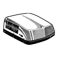
Details where the air conditioner is designed for installation and general operating considerations.

SPECIFICATIONS

2. PRECAUTIONS

General Installation Precautions

Highlights critical safety measures and prohibitions during installation.

3. CHOOSING LOCATION FOR THE AIR CONDITIONER/HEAT PUMP

Location Selection Criteria

Factors to consider when choosing the installation site on an RV roof.

4. AIR DISTRIBUTION SYSTEM SIZING & DESIGN

Duct System Design Requirements

Specifies requirements for duct material, insulation, sealing, and openings.

5. AIR DISTRIBUTION SYSTEM INSTALLATION

Roof and Ceiling Opening Preparation

Details the process for cutting and framing roof and ceiling openings for installation.

5. AIR DISTRIBUTION SYSTEM INSTALLATION

Installing Air Distribution Ducts

Instructions for installing air distribution ducts in the RV roof cavity.

6. COMFORT CONTROL CENTER™™, REMOTE SENSOR & CABLE INSTALLATION

Location Selection for CCC and Sensor

Guidelines for choosing optimal locations for the control center and remote sensors.

Control Cable Specifications and Preparation

Details on the type of cable and connectors required for the control system.

Wiring Cable Installation Procedures

Step-by-step instructions for routing and connecting control system wiring.

7. PLACING THE AIR CONDITIONER ON THE ROOF

Unit Placement and Handling

Instructions for safely removing, lifting, and positioning the air conditioner unit on the RV roof.

8. COLD CONTROL INSTALLATION

Installation for 520, 530, 579, 590, 591 & 595 Series

Specific steps for installing the freeze control sensor for certain model series.

Installation for 600 & 630 Series

Specific steps for installing the freeze control sensor for the 600 and 630 series.

9. WIRING OF CONTROL SYSTEM

115 VAC Supply Connection

Instructions for connecting the main 115 VAC power supply to the control system.

9. WIRING OF CONTROL SYSTEM

115 VAC Supply Wire Routing and Connection

Details on routing AC power supply lines and making secure wire connections.

Low Voltage Wire Connections

Procedure for connecting various low voltage wires for different functions like furnace and EMS.

Comfort Control Center™ Installation

Steps for mounting the CCC base plate and connecting the control cable.

9. AIR CONDITIONER INSTALLATION

Ceiling Template Installation (3105007/3105935 Series)

Steps for preparing and installing the ceiling template for specific return air cover models.

Foam Divider and Ceiling Template (3308120 Series)

Instructions for installing foam divider and ceiling template for Genesis Air Filtration System.

9. AIR CONDITIONER INSTALLATION

Divider Plate and Bolt Tightening (3105007/3105935 Series)

Procedure for installing the divider plate and tightening mounting bolts for specific models.

Control Box and Bolt Tightening (3308120 Series)

Steps for mounting the control box and tightening bolts for the Genesis Air Filtration System.

9. AIR CONDITIONER INSTALLATION

Inside Decorative Cover and Sealing (3105007/3105935 Series)

Instructions for installing the inside decorative cover and sealing the divider plate.

Inside Decorative Cover Installation (3308120 Series)

Steps for installing the inside decorative cover and connecting wiring for the Genesis Air Filtration System.

9. AIR CONDITIONER INSTALLATION

Final Assembly and Checks (3105007/3105935 Series)

Completing the installation by securing the control box and cover for specific models.

Final Assembly and Checks (3308120 Series)

Completing the installation for the Genesis Air Filtration System, including filter and handle.

10. SYSTEM CONFIGURATION, RESET & CHECKOUT

Electronic Control Configuration

Guide to setting dip switches for various system options and configurations.

System Reset Procedures

Steps to perform a system reset after configuration changes for proper operation.

System Checkout Verification

Ensuring all system features function correctly after installation and configuration.

11. WIRING DIAGRAMS

Electronic Field Wiring Diagram

Diagram illustrating the electronic field wiring connections for the control system.

Unit Field Wiring Diagram (A/C)

Diagram showing the field wiring connections for the air conditioner unit.

Heat Pump Field Wiring Diagrams

Wiring diagrams specific to Penguin and Brisk Air heat pump models.

Related product manuals