Do you have a question about the Dometic 541816 and is the answer not in the manual?
Learn to identify safety alerts and potential injury hazards using symbols and signal words for safe operation.
Grasp the meaning of signal words (Warning, Caution, Notice) to comprehend the severity of safety messages and potential outcomes.
Follow all safety information and instructions, adhering to applicable codes for safe installation and operation.
Adhere to warnings regarding qualified service, product modification, and authorized accessories for safe usage.
Detailed specifications including model number, capacity, electrical ratings, and component data for various units.
Specifies the necessary roof opening size, framing, and clearance for unit installation to ensure structural integrity.
Guidelines for selecting the optimal roof location based on RV size, heat gain, and personal comfort.
Details on routing and connecting 120 Vac supply wire, 12 Vdc supply wire, and communication cables for proper system function.
Procedures for installing thermostats, optional sensors, and communication cables for system control.
Instructions for safely connecting the 120 Vac power supply, including warnings and grounding requirements.
Specific steps for connecting low voltage wires for the LCD SZ system, including sensor and thermostat wiring.
Detailed instructions for connecting low voltage wires for the CCC 2 system, including sensors and communication cables.
Procedures for resetting the CCC 2 system after configuration and performing a system checkout to verify functionality.
Factors affecting the air conditioner's performance, including RV size, insulation, and external heat sources.
Information on condensation formation, manufacturer's responsibility, and measures to reduce interior condensation.
A basic overview of electrical connections between the RV, air conditioner, and thermostat.
Specific wiring diagrams for various Dometic unit models, detailing component connections.
Wiring schematics for electronic control kits, illustrating connections for different system types.
| Model | 541816 |
|---|---|
| Hertz | 60 Hz |
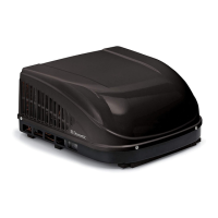
| Category | Air Conditioner |
| Cooling Capacity | 13, 500 BTU |
| Voltage | 115 V AC |
| Control Type | Digital thermostat control |
| Noise Level | 58 dB |