EasyManua.ls Logo

Dometic 651515.301 User Manual

Dometic 651515.301
11 pages
To Next Page IconTo Next Page
Page #1 background imageLoading...
Page #1 background image
1
641515, 641516, 641535, 651515 & 651516 Installation Instructions
This manual must be read and
understood before installation,
adjustment, service, or mainte-
nance is performed. This unit must
be installed by a quali ed service
technician. Modification of this
product can be extremely hazard-
ous and could result in personal
injury or property damage.
INSTALLATION
INSTRUCTIONS
Important: These Instructions
must stay with unit.
Owner read carefully.
RECORD THIS UNIT INFORMATION FOR
FUTURE REFERENCE:
Model Number
Serial Number
Date Purchased
Lire et comprendre ce manuel avant
de procéder à l'installation, à des ré-
glages, de l'entretien ou des répara-
tions. L'installation de cet appareil doit
être effectuée par un réparateur quali-
é. Toute modi cation de cet appareil
peut être extrêmement dangereuse et
entraîner des blessures ou dommages
matériels.
MODEL
641515, 641516, 641535
Roof Top Air Conditioners
651515, 651516
Roof-Top Heat Pump
used with
3106615 Air Distribution Box
3109228 Comfort Control Center
TM
MODELS
641515.301
641515.306
641516.301
641516.306
Form No. 3312127.000 10/08
(French 3312128.000)
©2008 Dometic, LLC
LaGrange, IN 46761
641516.331
641535.301
641535.306
651515.301
USA
SERVICE OFFICE
Dometic, LLC
2320 Industrial Parkway
Elkhart, IN 46516
574-294-2511
CANADA
Dometic, LLC
46 Zatonski, Unit 3
Brantford, ON N3T 5L8
CANADA
519-720-9578
For Service Center
Assistance Call:
800-544-4881
651515.306
651516.301
651516.306
651516.331
This Unit Is Designed For OEM Installation. All Initial
Installations Must Be Approved By Dometic, LLC
Question and Answer IconNeed help?

Do you have a question about the Dometic 651515.301 and is the answer not in the manual?

Dometic 651515.301 Specifications

General IconGeneral
BrandDometic
Model651515.301
CategoryAir Conditioner
LanguageEnglish

Summary

Installation Instructions

Safety Instructions

Information and instructions to help users reduce the risk of accidents and injuries.

Recognize Safety Information

Understand the meaning of the safety-alert symbol for potential personal injury.

Understand Signal Words

Learn the meaning of signal words (WARNING, CAUTION) for risk levels.

General Information

Details on product specifications, intended use, and factors affecting performance.

Unit Design and Intended Use

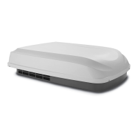
Details the unit's design for RV installation and intended purpose.

RV Heat Gain and Performance

Factors affecting RV temperature maintenance and performance optimization.

Condensation Information

Information regarding condensation formation and minimization within the RV.

Specifications

Installation Procedures

Installation Precautions

Essential safety and compliance guidelines before starting installation.

Choosing Unit Location

Guidelines for selecting an optimal and structurally sound location on the RV roof.

Roof Preparation

Instructions for preparing the RV roof, including cutting the opening.

Wiring Requirements

Details on electrical supply lines (120 VAC and 12 VDC) and their routing.

Comfort Control Center Installation

Steps for installing the Comfort Control Center and its associated cables.

Control Center Location

Guidance on selecting the optimal placement for the Comfort Control Center.

Control Cable Installation

Instructions for routing and terminating the control cable for the Comfort Control Center.

Control Center Mounting

Detailed steps for physically mounting the Comfort Control Center unit.

Placing Unit on Roof

Instructions for safely lifting and positioning the unit onto the prepared roof opening.

Installing the Unit

Steps for installing the air distribution box and connecting it to the unit.

Wiring the System

Connecting low voltage wires and the 120 Volt power supply to the unit.

Low Voltage Wire Connections

Connecting sensor, furnace, EMS, and control cables to the control box.

120 Volt Power Supply Connection

Connecting the main AC power supply to the unit, with safety warnings.

Air Box Installation

Installing the air box components, including filter-grilles.

System Configuration and Checkout

Configuring electronics, resetting the system, and verifying operation.

Electronic Control Kit Configuration

Setting dip switches on the electronic control kit for various equipment options.

System Reset Procedure

Performing a system reset after configuration changes for proper recognition.

System Checkout

Verifying all system features and functions after installation and configuration.

Related product manuals