Do you have a question about the Dometic 651815 and is the answer not in the manual?
Explains the safety alert symbol and its purpose to indicate potential injury hazards.
Defines signal words like WARNING, CAUTION, and NOTICE to indicate hazard levels.
Provides critical safety warnings regarding installation, servicing, and product modification.
Details critical safety precautions and steps for preparing the RV roof opening for unit installation.
Instructions for making low voltage and 120 Vac power connections to the unit.
Explains how to configure the system by setting dip switches based on installed options.
Procedures for resetting the system and performing a checkout to verify functionality.
| Model | 651815 |
|---|---|
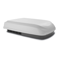
| Type | Rooftop Air Conditioner |
| Cooling Capacity | 15, 000 BTU/h |
| Refrigerant | R410A |
| Voltage | 115 V AC |
| Operating Temperature | 32°F to 122°F |