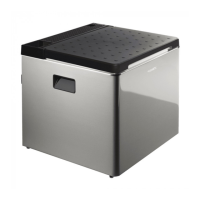
Technical description ACX35, ACX40, ACX40G
16
5.1 Connections
5.2 Control elements
When the cooler is connected to the AC mains, the required cooling level is set using
the cooling level controller (1).
➤ To increase the cooling level, turn the cooling level controller (1) clockwise.
For the maximum cooling level, turn the cooling level controller (1) clockwise as
far as it will go (position “7”).
➤ To decrease the cooling level, turn the cooling level controller (1) anticlockwise.
➤ To switch the cooler off, turn the cooling level controller (1) anti-clockwise as far
as it will go (position “0”).
When the cooler is connected to the DC power socket the cooling level cannot be
adjusted.
When the cooler is operated with gas, the required cooling level is set using the
temperature controller (2).
No. in
fig. 2, page 4
Description
1 AC connection cable
2 DC connection cable
3 Cover for control elements
4 Gas connection port (ACX35, ACX40 only)
5 Gas cartridge (ACX40G only)
6 Pilot light sight glass
No. in
fig. 3, page 5
Description
1 Cooling level controller
2 Temperature controller
3Ignition button
ACX35-ACX40-ACX40G-O-15s.book Seite 16 Freitag, 22. September 2017 6:24 18
 Loading...