10
EN
Furnaces
7
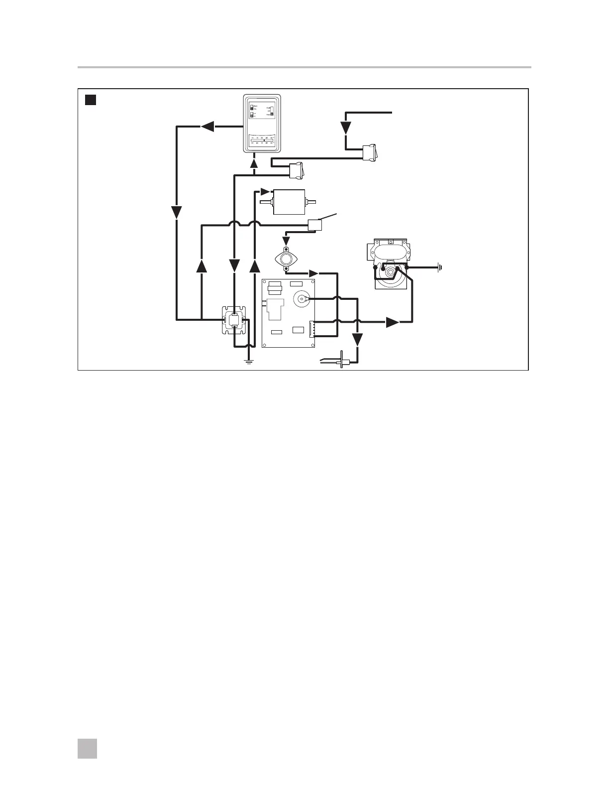
Thermostat
Relay
Ignition Control
+12 VDC
Motor
Sail
Switch
Valve
Limit
Switch
Circuit
Breaker
On/Off Switch
(some furnaces have
combination On/Off
switch circuit breakers)
(Limit and Sail Switch are
reversed in 79/80 series)
I
This diagram shows the external relay used in furnaces built prior to 07/2001.
Sequence of operation for DC models (standard units):
1. The ON/OFF switch allows power to pass through the circuit breaker to the thermostat.
2. The thermostat controls the operating circuit to the furnace by reacting to room temperature. When room
temperature is below the thermostat set-point, the contact closes to allow current to flow to the relay (the
relay can be either external or part of the ignition control board).
3. The circuit breaker limits the amperage draw of the motor.
4. The relay allows current to pass to the motor by closing a switch within the relay. Voltage from the thermostat
activates the relay to turn the fan on. This takes 1–25 seconds. On units that have the relay on the
ignition control board, there is only a 1–2 second delay.
5. Current flows to the motor to operate the blower. One end of the motor sha is for the blower wheel, and the
other side is for the combustion wheel.
6. Circulating air blows against the sail switch and closes the contacts, completing the circuit. The sail switch is a
safety device that ensures airflow before ignition.
7. The limit switch is a safety device that protects the furnace from overheating. The contacts in the limit switch open
at a given temperature setting, shutting off power to the electronic ignition system that controls the gas valve. As
power is applied to the circuit board, the system does the following:
• A timing circuit allows the blower to purge the chamber (15–17 seconds).
• The circuit board supplies current to the gas valve and causes it to open. As the gas valve opens, the circuit
board sends a high-voltage spark to the electrode at the burner. The circuit board detects the presence of
a flame.
– If the flame is not sensed aer approximately six seconds, the valve will close and the chamber will be
purged of any gas. Aer three tries for ignition, the control will lock out for one hour, unless power is
removed or the thermostat has cycled. Shutting off the main power will restart the cycle.
 Loading...