9
EN
Furnaces
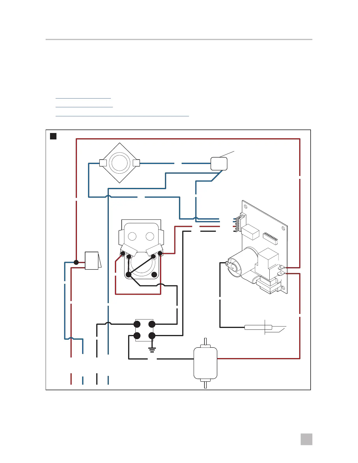
4.4 Sequence of operation/wiring diagrams
I
The wiring diagrams shown are the best representations of each furnace. Wire colors may vary.
Understanding the sequence of operations for a furnace is an important part of diagnosing the operational issues
occurring in the furnace. This section details the wiring and sequence of operation for each furnace type:
• DC Models (on page 9)
• AC Models (on page 12)
• Two-Stage Models (1522, 2334, and 2540) (on page 14)
DC Models
6
Limit Switch
Sail Switch
ON/OFF
Switch -
Breaker
Electrode
4-Pin Ground
Motor
Gas Valve
Ignition Control
Module
Blue
Red
Red
Red
Red
Red
BLO
PWR2
TH (pin)
AIR (pin)
GND (pin)
V1 (pin)
Red
Blue
Blue
Blue
Blue
+12 VDC
+Thermostat
-12 VDC
-Thermostat
Black
Black
Black
Black
Black
 Loading...