USE INSTA L L ATION
MAIN T E NANCE
ENGLISH
5
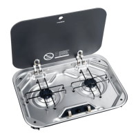
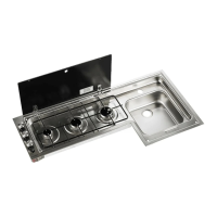
FIXING
The appliance must be secured by means of the fastening screws (FIG. 3 - PAG. 29):
1) insert the appliance in the unit;
2) tighten the screws.
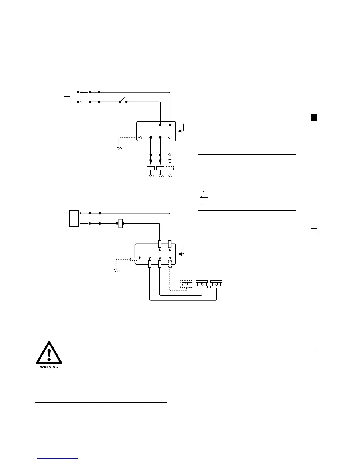
ALWAYS DISCONNECT THE ELECTRIC SUPPLY BEFORE ANY TYPE OF
INTERVENTION ON THE UNIT
LABEL ALL WIRES PRIOR TO DISCONNECTION WHEN SERVICING CONTROLS.
WIRING ERRORS CAN CAUSE IMPROPER AND DANGEROUS OPERATION.
VERIFY PROPER OPERATION AFTER SERVICING.
If polarity is incorrect electronic igniter will not function.
R = RED Wire
G = GREEN WITH YELLOW STRIPES Wire
(only for three burner models)
W = WHITE Wire
BK = BLACK Wire
= WIRE Connection
= Wired by Installer
=
only for three burner models
SCHEMATIC DIAGRAM
CONNECTION DIAGRAM
W W W
TOP BURNERS
+
+
-
-
BKW BK
SWITCH
RBK
12 VOLT
BATTERY
IGNITION
MODULE
G
CONNECTORS
W W W
TOP BURNERS
+
+
-
-
BKW BK
SWITCH
RBK
IGNITION
MODULE
G
SPARK ELECTRODES
12 V
WIRING DIAGRAM:
 Loading...