C.
D.
E.
F.
G.
Close the gas vatve by turning the knob
‘A'.
back to
the
‘OFF’
position. (See FIG.
9).
Wait one minute, then disconnect the 12 volt DC
power. (See FIG. 6 and
6A).
Remove burner cover plate. (See FIG. 6 and
6A).
Open the gas valve by turning knob
‘A’
to the
‘GAS’ position without pushing button
‘C’.
(See
FIG. 9). The reignitor should not be sparking. Apply
commercial leak-check bubble solution to the
burner jet. (See FIG. 8). Be careful not to damage
burner jet.
No bubbles should appear at the opening of the
burner jet. Bubbles indicate a defective gas safety
shutoff and service is required.
If no bubbles were present at the burner jet, rinse
the orifice with water. Replace the burner cover
plate. Reconnect the 12 volt DC power supply to the
refrigerator. See Section A. Installation, Item 11, 12
Volt DC Connection. Start the refrigerator by
following the instructions for gas operation with
automatic reignitor. Normal gas operation should
now return. Allow the burner to operate a minimum
of five minutes.
WARNING
DO NOT USE A FLAME TO CHECK
FOR GAS LEAKS.
L
10.
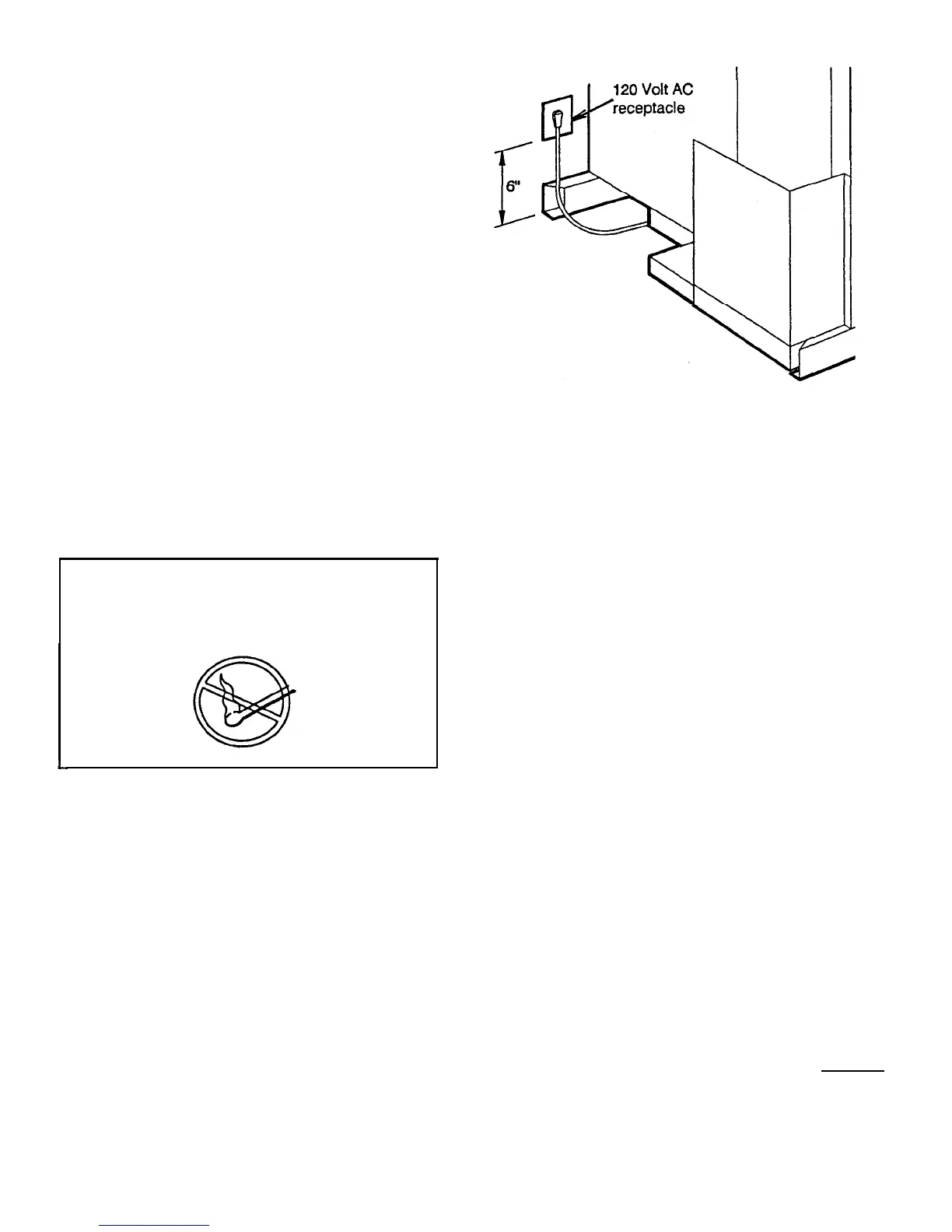
120 Volt AC Connection
The refrigerator is equipped with a three prong
(grounded) plug for protection against shock hazards
and should be plugged directly into a properly grounded
three-prong receptacle. DO NOT cut off
or
remove the
grounding prong from this plug. The free length of the
cord is 2 feet and therefore recommended that the
receptacle be located to the left side of the refrigerator
(viewed from the rear) and approximately 6 inches from
the floor. (See FIG. 10). This allows easy accessibility
through the vent door. The cord should be routed to
avoid contacting the burner cover, flue cover, or any
other components that could damage the cord
insulation.
FIG. 10
l
6”
11.
12 VOLT DC CONNECTION
n
P-WAY REFRIGERATOR MODELS
On 2-way refrigerator Models
RM2510,
RM2610
and
RM2810,
12 volts DC must be connected to the
refrigerator to provide power for operation of the
automatic reignitor. On these units there is one terminal
block marked 12 volts, located on the back of the
refrigerator cabinet. (See FIG. 6
&
6A).
The reignitor must be connected to the battery
circuit with a maximum fuse size of 3 amps and a
minimum wire size of 14 gauge.
n
3-WAY
REFRIGERATOR MODELS WITH
AUTOMATIC
REIGNITOR
On 3-way refrigerator models with automatic reignitors,
there are
two
terminal blocks for 12 volt DC. The 12 volt
DC terminal block on the back of the refrigerator cabinet
is for the reignitor; and the 12 volt DC terminal block
located under a plastic cover on the back of the
refrigerator is for the refrigerator heater. See FIG. 6 and
6A).
The refrigerator must be connected by a separate
circuit to the battery with two wires of adequate capacity
to avoid voltage drop when the 12 volt DC heater is
being operated. The wire gauge should be chosen with
consideration to the length, refer to the above Table for
wire size. The 12 volt DC circuit must be fused; refer to
the Table, on Page 7, for fuse size.
NOTE: The refrigerator Model
RM2410
does not
have an automatic reignitor. The 3-way model has
only one 12 volt DC terminal block located under
the plastic cover on the back of the refrigerator.
DO NOT
use the body or chassis of the
vehicle
as a
--
substitute for either of the two conductors.
DO NOT
connect any other electrical equipment or lighting to
the refrlgerator
circuit
6