SMP301-11 Technical description
9
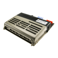
6.1 Product overview
6.2 Connections and displays
Item in
fig. 1, page 3
Element
1 Mounting holes
2 Fuse extractor
3 Brackets for 4 spare fuses
4 Clips for releasing of the cover
5 Cover of the connection space
6 Strain relief clamps
7 AC connection
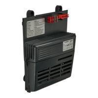
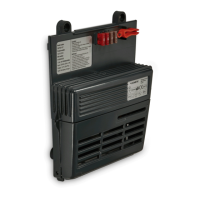
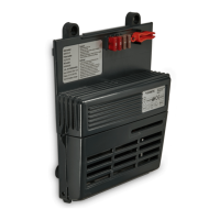
Item in
fig. 2, page 3
Element
1 LED – displays defective fuse
2 Plug-in fuse for output (maximum 30 A)
3 Jumper 7 (J7) – CI-bus connector
4 Jumper 9 (J9) – deactivates CI-bus (if J10 is not set)
5 Jumper 6 (J6) – deactivates J9 and J10; activates output when power
supply is provided (continuous operation)
6 Jumper 3 (J3) (for service personnel only)
7 Jumper 8 (J8) (for service personnel only)
8 Jumper 10 (J10) – activates CI-bus (if J9 is not set)
9 Output flat plug (positive terminal)
10 Output flat plug (negative terminal)
SMP301-11--IOM-7s.book Seite 9 Donnerstag, 21. November 2019 4:58 16
 Loading...